
User Guide Owner manual
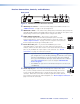
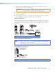

f Fiber optic connectors and LEDs —
CAUTION: These units output continuous invisible light, which may be harmful to
the eyes; use with caution. For additional safety, plug the attached dust
caps into the optical transceivers when the fiber cable is unplugged.
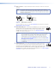
NOTES: • Ensure that you use the proper fiber cable for your transmitter/receiver
pair. Typically, singlemode fiber has a yellow jacket and multimode cable
has an orange or aqua jacket.
• Only one fiber optic cable, transmitter-Tx-to-receiver-Rx, is required for
video, audio, and serial command transmission. But, if you connect only
one fiber optic cable, or if your receiver is configured to daisy-chain the
optical signal:
• The HDMI signal output by the receiver is not HDCP-compliant.
• You will not receive RS-232 reports from the controlled device.
To receive responses from the controlled device and for HDCP
compliance, you need to install both fiber optic cables and leave link
2 enabled (via an SIS command to the receiver or using the FOX
Extenders Control Program).
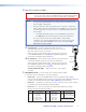
ä Tx (required) — For all one-way video, audio, and serial
Transmitter
to
Receiver
OPTICAL
Rx
Tx
LINK
LINK
OPTICAL
Rx
Tx
LINK
LINK
6a 6b
communications from the transmitter to the receiver, connect a
fiber optic cable to the Tx LC connector.
Connect the free end of this fiber optic cable to the Rx connector
on the FOXBOX HDMI receiver (item
o
on figure 4 on page 9) or
to any other compatible Extron FOX device.
ã Rx (optional) — Connect a fiber optic cable for all one-way return
serial communications from the receiver to the transmitter.
Connect the free end of this fiber optic cable to the Tx connector
on a FOXBOX Rx HDMI receiver (item
o
on figure 4 on page 9) or
to any other compatible Extron FOX device.
Tx Link and Rx Link LEDs — When lit, the link is active (light is
received).
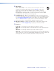
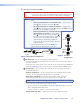
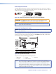
g EDID Minder switch — Set this switch to one of the positions below
to select the source of the DDC or a specific resolution.
• Position 0 — A user-recorded EDID that has been captured from the display
connected to the HDMI loop-thru connector on the transmitter (item
b
on figure 2
on page 5) or manually imported via an SIS command to the transmitter.
• Position 1 — The EDID is selected via one of the serial ports in the system using an
SIS command or the FOX Extenders Control Program.
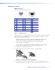
• Position 2 - F — Specify a resolution. The table below identifies the switch
positions and the associated resolutions.
Pos. Source or resolution Pos. Resolution Pos. Resolution
0 User recorded EDID 6 1280 x 800 C 1600 x 1200
1 RS-232 7 1280 x 1024 D 1680 x 1050
2 800 x 600 8 1360 x 768 E 1920 x 1080 (1080p)
3 1024 x 768 9 1366 x 768 F 1920 x 1200
4 1280 x 720 (720p) A 1400 x 1050
5 1280 x 768 B 1440 x 900
FOXBOX Tx/Rx HDMI • Installation and Operation 7