User Guide Fiber Optic Extenders FOXBOX Tx / Rx HDMI High Resolution Fiber Optic Transmitters and Receivers 68-1984-01 Rev.
Safety Instructions • English Warning This symbol is intended to alert the user of important operating and maintenance (servicing) instructions in the literature provided with the equipment. Power sources • This equipment should be operated only from the power source indicated on the product. This equipment is intended to be used with a main power system with a grounded (neutral) conductor. The third (grounding) pin is a safety feature, do not attempt to bypass or disable it.
FCC Class A Notice This equipment has been tested and found to comply with the limits for a Class A digital device, pursuant to part 15 of the FCC Rules. Operation is subject to the following two conditions: 1. This device may not cause harmful interference. 2. This device must accept any interference received, including interference that may cause undesired operation.
Conventions Used in this Guide Notifications the following are used: DANGER: A danger indicates a situation that will result in death or severe injury. WARNING: A warning indicates a situation that has the potential to result in death or severe injury. CAUTION: A caution indicates a situation that may result in minor injury. ATTENTION: Attention indicates a situation that may damage or destroy the product or associated equipment. NOTE: TIP: A note draws attention to important information.
Contents Introduction............................................................ 1 Remote Control.................................................... 17 About this Guide................................................. 1 About the FOXBOX Tx/Rx HDMI........................... 2 Transmitter....................................................... 2 Receiver........................................................... 2 Both Units........................................................ 3 System Compatibility...
FOXBOX Tx/Rx HDMI • Contents vi
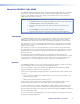
Introduction CAUTION: The FOXBOX Tx/Rx HDMI units output continuous invisible light, which may be harmful to the eyes; use with caution. • Do not look into the rear panel fiber optic cable connectors or into the fiber optic cables themselves. • Plug the attached dust caps into the optical transceivers when the fiber cable is unplugged.
About the FOXBOX Tx/Rx HDMI The FOXBOX HDMI Fiber Optic Extender is an ultra-high performance fiber optic transmitter and receiver set for long haul transmission of HDCP-compliant HDMI video, audio, and RS-232 control signals over fiber optic cabling. The transmitter and receiver can extend HDMI signals up to 30 km (18 miles). NOTE: For HDCP compliance: • A FOXBOX HDMI or PowerCage FOX HDMI transmitter must be paired with a FOXBOX HDMI or PowerCage FOX HDMI receiver.
Both Units The transmitter and receiver have many controls, including image and audio adjustments, that are available under RS-232 Simple Instruction Set (SIS™) control. Both units have image, audio, fiber light status, and lost-light alarm indicators. System Compatibility The FOXBOX Tx HDMI transmitter operates in either of two modes, selected under RS-232 control, for compatibility with other, non-HDMI, units: • Plus — Support resolutions up to 1920 x 1200 @ 60Hz.
Features Ultra high performance — Offers pixel-for-pixel HDMI or DVI-D (with an adapter) video transmission, up to 1920 x 1200 at 60 Hz (in Plus mode) or 1600 x 1200 at 60 Hz (in nonplus mode). Video input — The transmitter accepts a single link of HDMI or DVI-D video. Loop-through on transmitter — The transmitter has an HDMI loop-through on a HDMI connector that allows connection of a local monitor.
Installation and Operation This sections details the installation of the FOXBOX Tx/Rx HDMI, including: • Installation Overview • Connections • Operation Installation Overview Follow these steps to install and set up an Extron FOXBOX HDMI transmitter and receiver system for operation: 1. Turn off all of the equipment. Ensure that the video sources and the output display are all turned off and disconnected from the power source. 2.
c Audio connector — Plug an audio input into the transmitter via this stereo mini jack connector. NOTE: See figure 3 to identify the tip, ring, and sleeve when you are making connections for the transmitter from existing audio cables. A mono audio connector consists of the tip and sleeve. A stereo audio connector consists of the tip, ring, and sleeve. Tip (+) Ring (-) Tip (+) Sleeve ( ) Sleeve ( ) RCA Connector Figure 3. 3.
f Fiber optic connectors and LEDs — CAUTION: These units output continuous invisible light, which may be harmful to the eyes; use with caution. For additional safety, plug the attached dust caps into the optical transceivers when the fiber cable is unplugged. NOTES: • Ensure that you use the proper fiber cable for your transmitter/receiver pair. Typically, singlemode fiber has a yellow jacket and multimode cable has an orange or aqua jacket.
h 50Hz DIGITAL DIP switches — AUDIO 50 Hz / 60 Hz switch — This switch selects the vertical refresh rate of the resolution selected by the EDID Minder hex switch (item g on figure 2 on page 5). Up selects the 50 Hz rate and down selects the 60 Hz refresh rate. 60Hz ANALOG Audio switch — This switch selects which audio input, the audio embedded in the HDMI input or the analog audio, is sent to the receiver. Up selects the digital (embedded) audio and down selects the analog audio.
Receiver Connections, Controls, and Indicators Rear panel 19 Rx OPTICAL 12 FOXBOX Rx HDMI OFF 14 OUTPUTS HDMI AUDIO ON LINK Tx LINK POWER 12V 1.0A MAX 13 17 L HDMI AUDIO 15 16 R RS-232 OVER FIBER ALARM Tx Rx 1 2 18 REMOTE RS-232 Tx Rx Figure 4. FOXBOX Rx Receiver Rear Panel Features l HDMI Output connector — Connect a video display to this HDMI connector. See “HDMI connector“ on page 12 for pin assignments.
q Fiber optic connectors and LEDs — CAUTION: These units output continuous invisible light, which may be harmful to the eyes; use with caution. For additional safety, plug the attached dust caps into the optical transceivers when the fiber cable is unplugged. NOTES: • You can connect the transmitter to one or more receivers in one of three ways: • One way (transmitter-Tx-to-receiver-Rx) only — Connect fiber cable 17a (from transmitter connector ä) only.
r Remote RS-232 port — For serial control of the receiver, connect a host device, such as a computer, touch panel control, or RS-232 capable PDA, to the transmitter via this 3-pole captive screw connector. See “RS-232 connections“ on page 13 to wire this connector. See “Remote Control“ on page 17 for SIS commands and software control. s DC power connector — Plug the included external 12 VDC power supply into this connector. See “Power supply wiring“ on page 15, to wire the connector.
Making Connections HDMI connector Figure 8 defines the HDMI pin assignments.
3. Place the LockIt lacing bracket on the screw and against the HDMI connector, then tighten the screw to secure the bracket (c). ATTENTION: Do not overtighten the HDMI connector mounting screw. The shield to which it fastens is very thin and can easily be stripped. 4. Loosely place the included tie wrap around the HDMI connector and the LockIt lacing bracket as shown (d). 5.
Audio output connector See figure 12 to properly wire a captive screw output connector. The connector is included with transmitter, but you must supply the audio cable. Use the supplied tie-wrap to strap the audio cable to the extended tail of the connector. NO GROUND HERE L R R Do not tin the wires! L Tip Ring Sleeves Tip Ring Tip Sleeves Tip NO GROUND HERE Unbalanced Stereo Output Balanced Stereo Output Figure 12.
See “Remote Control“ on page 17 for definitions of the SIS commands (serial commands to control the transmitter via this connector) and software control. Power supply wiring ATTENTION: Always use power supplies specified by Extron for the FOXBOX units. Use of an unauthorized power supply voids all regulatory compliance certification and may cause damage to the supply and the unit. Figure 14 shows how to wire the power connector.
Use the supplied tie wrap to strap the power cord to the extended tail of the connector. Alternatively, an optional Extron PS 124 Universal 12 VDC Power Supply, part #60-1022-01, can power multiple Extron 12 VDC devices using only one AC power connector. Operation After the transmitter, all receivers, and their connected devices are powered up, the system is fully operational.
Remote Control This section describes the remote control operation of the FOXBOX HDMI and, including: • Simple Instruction Set Control • FOX Extenders Control Program The transmitter and receiver each have a front panel Configuration port, a 2.5 mm mini stereo jack (see “Front panel Configuration Ports“ in the “Installation and Operation” section. The receiver has a rear panel Remote RS-232 port, a 3-pole captive screw connector (see “RS-232 connections“ in the “Installation and Operation” section.
Simple Instruction Set Control Host-to-Unit Instructions SIS commands consist of one or more characters per field. No special characters are required to begin or end a command character sequence. When a command is valid, the unit executes the command and sends a response to the host device. All responses from the unit to the host end with a carriage return and a line feed (CR/LF = ]), which signals the end of the response character string. A string is one or more characters.
Unit-initiated Messages When a local event, such as an equipment power-up, occurs, the unit responds by sending a message to the host. The unit-initiated messages are listed below: (c) Copyright 20nn, Extron Electronics FOXBOX Tx HDMI, Vx.xx, 60-1174-xx]] - or (c) Copyright 20nn, Extron Electronics FOXBOX Rx HDMI, Vx.xx, 60-1174-xx]] The connected unit issues the appropriate copyright message (above) when it first powers on. Vx.
Command/Response Table for Transmitter SIS Commands Command ASCII Command Response (host to unit) (unit to host) Request EDID and refresh rate switch positions Example: EStat} EdidMdrX!•VrateX@] EStat} EdidMdr15•Vrate2] Request EDID switch position Request Refresh rate switch position E2Stat} E3Stat} X!] X@] Additional description Switch status EDID switch is set to 15 (1080p) and the vertical rate switch is set to 2 (60 Hz).
Command/response table for Transmitter SIS commands (continued) Command ASCII Command Response (host to unit) (unit to host) Additional description Audio input gain and attenuation NOTES: • The set gain (G) and set attenuation (g) commands are case sensitive. The increment level, decrement level, and show level are not case sensitive. • When the controlling PC is connected to the receiver, the PowerCage FOX can perform this command only if the receiver-Tx-totransmitter-Rx fiber cable is connected.
Command/response table for Transmitter SIS commands (continued) Command ASCII Command Response (host to unit) (unit to host) Additional description I 1LnkX1!•2LnkX1!•VidX1!•AudX1!•X1#•Tx] Information requests Information request The unit responds with the current status (signal detected) of optical link 1, optical link 2, the video input, and the audio link; the fiber optic transmission mode (singlemode or multimode); and the device type (Tx). Show firmware version Example: Q Q X1$] 1.
Symbol definitions for receiver SIS commands ] } = Carriage return/line feed = Carriage return (no line feed) = Pipe (can be used interchangeably with the } character) | • E W X( X1! X1@ X1# X1$ X1% X1^ X1& X1* X1( = Space (hard) character = Escape key (hex 1B) = Can be used interchangeably with the E character = Mute/auto memory status and enable or disable status 0 = off or disable 1 = on or enable = Link and input status 0 = link or input not detected 1 = link or input detected = Internal t
Command/response table for Receiver SIS commands (continued) Command ASCII Command Response (host to unit) (unit to host) X1*, X1*. SprX1*] RprX1*] 55*0# 55*1# 55# Img0] Img1] 1Z 0Z Z Amt1] Amt0] Additional description Memory presets Save preset Recall preset Command code is a comma. Command code is a period.
Command/response table for Receiver SIS commands (continued) Command ASCII Command Response (host to unit) (unit to host) Additional description Video shutdown delay NOTES: • The Set Video Delay command delays the digital video to help monitors sync correctly during an input rate change. • Only video is delayed; embedded audio is not delayed. Set delay Example: 3*X2!# 3*3# DlyX2!] Dly3] View delay 3# X2!] Delay video by an interval of X2!. Delay video by an interval of 0.75 seconds (3 x 0.
FOX Extenders Control Program The Extron FOX Extenders program, which communicates with the transmitter and receiver pair via the Remote RS-232 port of either unit provides an easy way to operate the pair. The program is compatible with Windows 2000, Windows XP, or later. Updates to this program can be downloaded from the Extron Web site (www.extron.com). Installing the Software The program is contained on a DVD. To install the software, insert the DVD into the drive.
Starting the Program Start the Extron FOX Extenders program as follows: 1. Click Start > Programs > Extron Electronics > FOX Extenders Control Program > FOX Extenders. The Communication Setup window appears (see figure 15). Figure 15. Communication Setup Window 2. Select the Com port to which your transmitter or receiver is connected. Click OK. The FOX Extenders Control Program window appears (see figure 16). Figure 16.
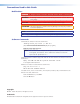
Status area Figure 17. Status Area The status area provides indications of the connection status. • HDMI indicator — This indicator is green when the transmitter detects a sync signal on its HDMI video input • Audio indicator — This indicator is green when the transmitter detects a low level audio signal for a short period. This indicator goes dark if the audio signal drops below the minimum threshold for a short period.
Audio Adjustment area NOTE: The Audio Adjustment area controls are available only if you are connected to the transmitter. Audio Gain/Attenuation slider — Click and drag the Audio Gain/ Attenuation slider control to select the input audio gain or attenuation value, from -18 dB to +10 dB in 1.0 dB increments. Memory Preset area NOTE: The Memory Preset area controls are available only if you are connected to the receiver. The Memory Preset area provides a means to save and recall memory presets.
HDCP area NOTE: • The HDCP Authorized controls are available only if you are connected to the transmitter. • The HDCP Notification controls are available only if you are connected to the receiver. Both sets of radio buttons cannot be available for selection at the same time. HDCP Authorized radio buttons — The HDCP authorized function determines whether the transmitter operates as an HDCP authorized device or not. An HDCP authorized device allows an HDMI source to output HDCP-encrypted video.
Video Bit Depth area NOTE: The Video Bit Depth area radio buttons are available only if you are connected to the receiver. The Video Bit Depth radio buttons allow you to force the bit depth to 8 bits or to set it to auto. Advanced tab functions Click the Advanced tab to access the functions described below. NOTE: The Advanced functions are available only if you are connected to the receiver.
Firmware upgrade Firmware can be upgraded for each unit via the front panel Configuration port on that unit using the Extron Firmware Loader utility from the Windows-based control program. NOTE: Your computer must be connected directly to the unit for the firmware to be updated. Downloading the firmware from the Web site To obtain the latest version of firmware for your FOXBOX unit: 1. Visit the Extron web site, www.extron.
4. Follow the instructions on the rest of the download screens to download the firmware update from the Extron Web site, start the Extron Installation Program to extract the firmware file, and place it in a folder identified in the program window. NOTE: Note the folder to which the firmware file is saved (see figure 21). Folder where firmware is installed Figure 21.
2. If you have not previously updated firmware for the FOXBOX unit before, on the Add Device screen (see figure 22), select the RS-232 tab. Figure 22. Add Device Screen If you have previously updated firmware for this model, click Cancel. The Firmware Loader window appears. Proceed to step 5. NOTE: Although the screen also has a TCP/IP tab, the FOXBOX unit does not have a LAN port. Do not select the TCP/IP tab. 3.
6. Navigate to and select the new firmware file. Click Open. The Choose Firmware File window closes. NOTE: When downloaded from the Extron Web site, the firmware is placed in a subfolder of C: \Program Files\Extron\Firmware. ATTENTION: The firmware file must have a .S19 extension. Other file types can cause the unit to stop functioning. 7. In the Firmware Loader window, click Begin (see figure 25). The Total Progress and Progress status bars show the progress of the upload.
Reference Information This section discusses the specifications, part numbers, and accessories for the FOXBOX Tx/Rx HDMI. Topics that are covered, include: • Specifications • Part Numbers • Mounting the Units Specifications NOTES: • The analog audio signal(s) is (are) digitized in the transmitter, sent through the fiber cable, and converted back to analog audio in the receiver. • These transceivers are class 1 laser products. They meet the safety regulations of IEC-60825, FDA 21 CFR 1040.
Video NOTE: *Appropriate HDMI to DVI-D cables or adapters are required for DVI signal input/output. Resolution range ���������������������������� Up to 1920x1200 or 1080p @ 60 Hz pixel for pixel Formats ������������������������������������������ RGB, YCbCr, and xvYCC digital video EDID ����������������������������������������������� Supports emulation of custom or factory preset Extended Display Identification Data (EDID) tables.
Control/remote Serial control ports on each unit (transmitter and receiver) Control ������������������������������������ 1 RS-232, 2.5 mm mini stereo jack (front panel) 1 RS-232, 3.5 mm captive screw connector, 3-pole (rear panel) (receiver only) Pass-through ���������������������������� 1 RS-232, 3.
Regulatory compliance Safety �������������������������������������� EMI/EMC ��������������������������������� Environmental �������������������������� MTBF ��������������������������������������������� Warranty ���������������������������������������� NOTES: CE, c-UL, FDA Class 1, UL CE, C-tick, FCC Class A, ICES, VCCI Complies with the appropriate requirements of RoHS, WEEE 30,000 hours 3 years parts and labor • All nominal levels are at ±10%. • Specifications are subject to change without notice.
These items are included in each order for a FOX Rx HDMI receiver: Included parts Part number 12V, 1A external power supply, with IEC power cord (qty. 1)* SFP Module (SM or MM, depending on the model) LockIt Lacing Brackets and tie-wrap (qty. 1) 21-235-01LF Captive screw 5-pole connectors (qty. 2) 10-703-12 Captive screw 3-pole connector (qty. 1) 10-319-13LF 10' LC-LC duplex patch cable (SM or MM, depending on the model) Rubber feet (qty.
Bulk fiber cable and termination tools RG6 Super High Resolution Cable Part Number OM4 MM P/2K Plenum 2 km (6,562 foot) Spool 22-225-02 SM P/2K Plenum 2 km (6,562 foot) Spool 22-223-02 Fiber Optic Termination Kit Termination Kit 100-656-01 QLC MM/10 Multimode, qty. 10 101-018-01 QLC SM/10 Singlemode, qty.
UL Guidelines for Rack Mounting The following Underwriters Laboratories (UL) guidelines pertain to the installation of a FOXBOX Tx/Rx unit into a rack. 1. Elevated operating ambient — If installed in a closed or multi-unit rack assembly, the operating ambient temperature of the rack environment may be greater than room ambient. Therefore, consider installing the equipment in an environment compatible with the maximum ambient temperature specified by Extron (Tma = +122 °F [+50 °C]). 2.
Extron Warranty Extron Electronics warrants this product against defects in materials and workmanship for a period of three years from the date of purchase.