User Guide Fiber Optic Extenders FOXBOX SR HDMI Fiber Optic Scaling Receiver for HDMI, Audio, and RS-232 68-1990-01 Rev.
Safety Instructions • English WARNING: This symbol, , when used on the product, is intended to alert the user of the presence of uninsulated dangerous voltage within the product’s enclosure that may present a risk of electric shock. ATTENTION: This symbol, , when used on the product, is intended to alert the user of important operating and maintenance (servicing) instructions in the literature provided with the equipment.
FCC Class A Notice This equipment has been tested and found to comply with the limits for a Class A digital device, pursuant to part 15 of the FCC rules. The Class A limits provide reasonable protection against harmful interference when the equipment is operated in a commercial environment. This equipment generates, uses, and can radiate radio frequency energy and, if not installed and used in accordance with the instruction guide, may cause harmful interference to radio communications.
Software Commands Commands are written in the fonts shown here: ^AR Merge Scene,,Op1 scene 1,1 ^B 51 ^W^C [01] R 0004 00300 00400 00800 00600 [02] 35 [17] [03] E X! *X1&* X2)* X2#* X2! CE} NOTE: For commands and examples of computer or device responses mentioned in this guide, the character “0” is used for the number zero and “O” represents the capital letter “o.” Computer responses and directory paths that do not have variables are written in the font shown here: Reply from 208.132.180.
Contents Introduction............................................................ 1 Remote Control.................................................... 20 About this Guide................................................. 1 About the FOXBOX SR HDMI............................... 2 System Compatibility....................................... 2 Cable Transmission Modes............................... 3 Features............................................................... 3 Simple Instruction Set Control.....
FOXBOX SR HDMI • Contents vi
Introduction WARNING: Risk of eye injury: The FOXBOX SR HDMI outputs continuous invisible light, which may be harmful to the eyes; use with caution. • Do not look into the rear panel fiber optic cable connectors or into the fiber optic cables themselves while the receiver is powered on. • Plug the attached dust caps into the optical transceivers when the fiber cable is unplugged.
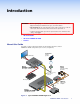
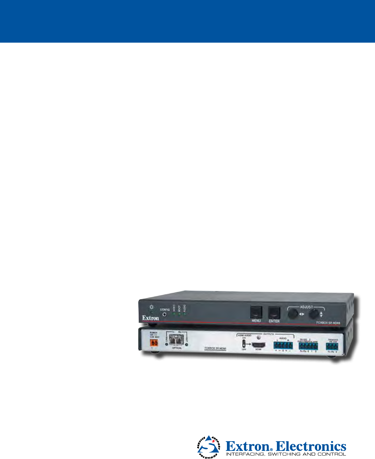
About the FOXBOX SR HDMI The FOXBOX SR HDMI is an ultra-high performance scaling fiber optic receiver that accepts a proprietary optical signal on a single LC connector from a compatible fiber optic transmitter or daisy-chained receiver located up to 30 km (18 miles) away. The receiver outputs a single link of HDMI video, digital audio (embedded in the HDMI output), analog audio, and RS-232 serial commands. The receiver can scale its video output to one of several resolutions and rates.
Cable Transmission Modes The receiver is further categorized by the type of fiber optic cable, multimode or singlemode, which defines the effective range of transmission: • Multimode (MM) — Long distance, up to 2 km (6,560 feet) (depending on the fiber cable) • Singlemode (SM) — Very long distance, up to 30 km (18.75 miles) NOTE: The multimode and singlemode units are physically and functionally identical, with the exception of the effective range of transmission.
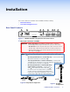
Installation This sections details the installation of the FOXBOX SR HDMI, including: • Rear Panel Features • Front Panel Configuration Port Rear Panel Features 8 2 4 5 6 7 OUTPUTS Rx HDMI AUDIO ON LINK Tx LINK POWER 12V 1.0 A MAX 3 1 FOXBOX SR HDMI OPTICAL OFF L AUDIO R RS-232 OVER FIBER ALARM Tx Rx HDMI 1 2 REMOTE RS-232 Tx Rx Figure 2.
NOTES: • Ensure that you use the proper fiber cable for your transmitter/receiver pair. Typically, singlemode fiber has a yellow jacket and multimode cable has an orange or aqua jacket. • Only one fiber optic cable, transmitter-Tx-to-receiver-Rx, is required for video, audio, and serial command transmission. However, if you connect only one fiber optic cable, or if your receiver is configured to daisy-chain the optical signal: • The HDMI signal output by the receiver is not HDCP-compliant.
e RS-232 Over Fiber port — If you want the FOXBOX to pass serial command signals to a slave device, for serial control of a projector for example, connect the slave device to the receiver via the first three leftmost poles (Tx, Rx, and _) of this 5-pole captive screw connector (see “RS-232 connections“ on page 8 to wire this connector).
Making Connections HDMI connector Figure 5 defines the HDMI pin assignments.
3. Place the LockIt lacing bracket on the screw and against the HDMI connector, then tighten the screw to secure the bracket (c). ATTENTION: Do not overtighten the HDMI connector mounting screw. The shield to which it fastens is very thin and can easily be stripped. 4. Loosely place the included tie wrap around the HDMI connector and the LockIt lacing bracket (d). 5.
Audio output connector See figure 9 to properly wire a captive screw output connector. The connector is included with the receiver, but you must supply the audio cable. Use the supplied tie-wrap to strap the audio cable to the extended tail of the connector. NO GROUND HERE R Tip Ring Sleeves Tip Ring L R NO GROUND HERE Unbalanced Stereo Output L Do not tin the wires! Tip Sleeves Tip Balanced Stereo Output Figure 9.
Power supply wiring ATTENTION: Always use power supplies specified by Extron for the FOXBOX units. Use of an unauthorized power supply voids all regulatory compliance certification and may cause damage to the supply and the unit. Figure 10 shows how to wire the power connector. Smooth Ridges A A Power Supply Output Cord SECTION A–A Tie Wrap 5 3 Captive Screw Connector Figure 10.
Front Panel Configuration Port AUDIO HDCP CONFIG VIDEO 1 Figure 11. FOXBOX SR Scaling Receiver Front Panel Features a Configuration port — Connect a controlling device, such as a PC, to this port via a 2.5 mm mini jack TRS RS‑232 cable for RS-232 protocol control of all FOXBOX functions. The optional 9-pin D to 2.5 mm mini jack TRS RS‑232 cable, part number 70-335-01 (figure 12) can be used for this connection.
Operation This sections details the installation of the FOXBOX SR HDMI, including: • Front Panel Indications and Controls • Operation Front Panel Indications and Controls The receiver has front panel LEDs that indicate power and signal status (see figure 13) and a menu system that is operated using the front panel controls and displayed on the connected output device. 1 3 4 5 ADJUST AUDIO HDCP CONFIG VIDEO 2 MENU ENTER FOXBOX SR HDMI Figure 13.
Operation After the transmitter, all receivers, and their connected devices are powered up, the system is fully operational. If any problems are encountered, verify that the cables are routed and connected properly, and that all display devices have identical resolutions and refresh rates. If your problems persist, call the Extron S3 Sales & Technical Support Hotline (see the contact numbers on the last page of this guide for the Extron office nearest you).
Menu and Submenus Figure 15 shows a flowchart of the submenus in the main menu system. Each submenu leads to one or more a series of submenus or to “slider” type status indicator bar controls that accomplish individual tasks or groups of tasks. NOTE: In figure 15, and all other flowcharts in this chapter, solid lines indicate screen changes initiated by the operator. Dashed lines indicate screen changes that are the result of a timeout function.
Auto Image submenu Figure 16 shows an overview of the Auto Image submenu and executing the Auto-Image™ function. Select Auto Image and press the Enter button twice to automatically size and center the input to fit the output resolution. No menu display Menu Menu EXTRON ELECTRONICS AUTO IMAGE FOXBOX SR HDMI Enter PICTURE CONTROLS Timeout USER PRESETS Timeout OUTPUT CONFIGURATION Timeout ADVANCED CONFIGURATION Timeout PRESS ENTER TO AUTO IMAGE Timeout Figure 16.
Size selection The Size selection allow you to adjust the horizontal and vertical size of the output. Rotate the Adjust [ knob while this submenu is active to size the image horizontally and the Adjust { to size the image vertically. Brightness and Contrast selection Rotate the Adjust [ knob while this submenu is active to increase and decrease the image brightness, from 0 through 255. Rotate the Adjust { to increase and decrease the image contrast, from 0 through 255.
Save submenu Rotate either Adjust knob while this submenu is active to select a preset number, from 1 through 30, and press the Enter button to save the current settings to the selected preset. Allow the screen to timeout without pressing the Enter button to exit without saving the settings. Clear submenu Rotate either Adjust knob while this submenu is active to select a preset number, from 1 through 30, and press the Enter button to erase the selected preset.
Advanced Configuration submenu Figure 20 shows an overview of the Advanced Configuration submenu and the available selections. No menu display Menu Menu EXTRON ELECTRONICS FOXBOX SR HDMI AUTO IMAGE Timeout TEST PATTERN NONE PICTURE CONTROLS Timeout BLANK OFF USER PRESETS Timeout FREEZE OFF OUTPUT CONFIGURATION Timeout ASPECT RATIO FILL ADVANCED CONFIGURATION Enter AUTO MEMORY ON FACTORY RESET HOLD ENTER MENU TIMEOUT 5 Figure 20.
Aspect Ratio submenu The Aspect Ratio submenu lets you specify how the scaler handles the aspect ratio of a scaled output. Rotate either Adjust knob while this submenu is active to select either Fill to force the input to automatically fill the output raster or Follow Input to display the input in its native aspect ratio. Auto Memory submenu The Auto Memory submenu provides a means to toggle the auto memory feature on or off. by rotating either Adjust knob while this submenu is active.
Remote Control This section describes the remote control operation of the FOXBOX SR HDMI, including: • Simple Instruction Set Control • Signal Processing Product Control Program The receiver has two serial ports: the front panel Configuration port, a 2.5 mm mini stereo jack (see “Front panel Configuration Port“ on page 11); and a rear panel Remote RS-232 port, a 3-pole captive screw connector (see “RS-232 connections“ on page 8).
Symbol Definitions ] = CR/LF (carriage return/line feed) } = Carriage return (no line feed) | • E W X! = Pipe (can be used interchangeably with the } character) = Space (hard) character = Escape key (hex 1B) = Can be used interchangeably with the E character = Mute status = Detail 0 = off (unmute) 1 = on (mute video and sync) 000 through 255 (default 128) 000 through 128 (default 64) = Horizontal and vertical position Range depends on selected output size 2 = on (mute video) X@ X# X$ X% X^ X& X
Unit-initiated Messages When a local event, such as an equipment power-up, occurs, the unit responds by sending a message to the host. The unit-initiated messages are listed below: (c) Copyright 20nn, Extron Electronics FOXBOX SR HDMI yy, Vn.nn, 60-1187-xx]] The receiver issues the copyright message (above) when it first powers on. yy is SM or MM. Vn.nn is the firmware version number; 60-1187-xx is the part number of the connected unit.
Command and Response Table for SIS Commands Command ASCII Command Response (host to unit) (unit to host) 1B 2B 0B B Blk1] Blk2] Blk0] EX@CONT} E+CONT} E–CONT} ECONT} ContX@] ContX@] ContX@] Additional description Video mute Mute video output Mute video and sync output Unmute video output Show video mute status X!] Blank the video output. Blank the video and suspend sync. Output video and sync. Video mute status is X!.
Command and response table for SIS commands (continued) Command ASCII Command Response (host to unit) (unit to host) Set the output rate EX&RATE} RateX&] Show the output rate ERATE} X&] Additional description Output scaler rate Select the output resolution and rate to X& (see the table below the Show command). See the table below.
Command and response table for SIS commands (continued) Command ASCII Command Response (host to unit) (unit to host) Additional description Output color bars Output grayscale Output crosshatch Output alternating pixels Output crop Turn test pattern off E1TEST} E2TEST} E3TEST} E4TEST} E5TEST} E0TEST} Test1] Test2] Test3] Test4] Test5] Test0] Show test pattern status ETEST} X1$] Set the unit to output the color bars test pattern. Set the unit to output the grayscale test pattern.
Command and response table for SIS commands (continued) Command ASCII Command Response (host to unit) (unit to host) Additional description On-screen display timeout Set menu timeout View menu timeout EX1&MDUR} EMDUR} MdurX1&] MdurX1&] Set the duration of the on-screen display. View the duration of the on-screen display. EmbedAudX1*] Show the position of the Audio switch: 0 = off (embedded audio is muted) or 1 = on (unmute).
Signal Processing Product Control Program The Extron Signal Processing Control Program, which communicates with the receiver via its Configuration port or Remote RS-232 port, provides an easy way to operate the receiver. The program is compatible with Windows 2000, Windows XP®, or later. Updates to this program can be downloaded from the Extron website (www.extron.com). Installing the Software The program is contained on a DVD. To install the software, insert the DVD into the drive.
2. Select the Com port to which your or receiver is connected. Click OK. The Signal Processing Product Control Program window appears (see figure 23). NOTE: The receiver does not have an Ethernet port. Do not select TCP/IP. Figure 23. Signal Processing Product Control Program Window Status area Figure 24. Status Area The status area provides indications of the connection status. • HDMI indicator — This indicator is green when the transmitter detects a sync signal on its HDMI video input.
The Status area also shows the receiver model (multimode or singlemode), and the position of the HDMI Audio (embedded audio) switch. Control tab functions Click the Control tab to access the functions described below. Output View area NOTE: The Output View area controls are available only if the receiver is connected to a transmitter with an active video input. The Output View area provides controls that let you scale and change the position of the displayed image.
I/O Configuration tab functions Click the I/O Configuration tab to access the functions described below. HDCP Notification area The HDCP Notification function enables a connected display to show a green or black screen if the transmitted HDMI video is HDCP encrypted and the display is not HDCP capable. Output Configuration area The Output Configuration area provides tools to select the output resolution, refresh rate, and HDMI format for the scaler (see figure 25). Figure 25.
Advanced Functions area Select the Executive Mode checkbox to lock all front panel controls except for using the Menu and Enter buttons to unlock the panel only. Select the Auto Memory checkbox to automatically apply saved position settings when the sensed input resolution changes. Aspect Ratio area Select the Fill radio button to force the input to automatically fill the output raster. Select the Follow radio button to display the input in its native aspect ratio.
Firmware Upgrade Receiver firmware can be upgraded via the front panel Configuration port using the Extron Firmware Loader utility from the Windows-based control program. Downloading the firmware from the website To obtain the latest version of firmware for your FOXBOX unit: 1. Visit the Extron website, www.extron.com, click the Download tab, and then click the Firmware link on the left sidebar menu (see figure 26). 1 1 Figure 26. Location of Firmware Upgrade Files 2.
4. Follow the instructions on the rest of the download screens to download the firmware update from the Extron website, start the Extron Installation Program to extract the firmware file, and place it in a folder identified in the program window. NOTE: Note the folder to which the firmware file is saved (see figure 29). Folder where firmware is installed Figure 29.
2. If you have not previously updated firmware for the FOXBOX unit, on the Add Device screen (see figure 30), select the RS-232 tab. Figure 30. Add Device Screen If you have previously updated firmware for this model, click Cancel. The Firmware Loader window appears. Proceed to step 5. NOTE: The receiver does not have an Ethernet port. Do not select TCP/IP. 3. From the drop-down menus on the RS-232 screen, select the appropriate Com port number and baud rate (the default is 9600). 4. Click OK.
6. Navigate to and select the new firmware file. Click Open. The Choose Firmware File window closes. NOTE: When downloaded from the Extron website, the firmware is placed in a subfolder of C:\Program Files\Extron\Firmware. ATTENTION: The firmware file must have a .S19 extension. Other file types can cause the unit to stop functioning. 7. In the Firmware Loader window, click Begin (see figure 33). The Total Progress and Progress status bars show the progress of the upload.
Reference Information This section discusses the specifications, part numbers, and accessories for the FOXBOX SR HDMI.
Mounting Accessories Mounting Kit Part Number ZipClip 100 Mounting Kit for PS Series Power Supplies (qty. 10) 101-002-01 RSU 126 6-inch deep 1U universal rack shelf kit 60-190-10 RSB 126 6-inch deep 1U basic rack shelf 60-604-11 RSU 129 9.5-inch deep 1U universal rack shelf kit 60-190-01 RSB 129 9.
Mounting the Unit ATTENTION: Installation and service must be performed by authorized personnel only. Either of the 1-inch high, half-rack width unit can be placed on a tabletop, mounted on a rack shelf, mounted to a projector bracket, or mounted under or through a desk or other furniture. Tabletop Use Affix the four included rubber feet to the bottom of the unit and place it in any convenient location.
Extron Warranty Extron Electronics warrants this product against defects in materials and workmanship for a period of three years from the date of purchase.