
User guide


FOX T USW 203 Universal Switcher • Operation 11
Operation
This section describes the front panel features of the FOX T USW 203 and describes front
panel operations. Topics in this section include:
• Front Panel Features
• Front Panel Operation
Front Panel Features
FOX T USW 203
FOX UNIVERSAL SWITCHER
AUTO
SWITCH
MODE
CONFIG
NORMAL
1 2
AUTO
SIGNAL
HDCP
STATUS
3
123
CA B D
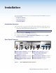
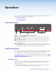
Figure 6. FOX T USW 203 Front Panel Features
A
Auto Switch LED indicator — Lights when the transmitter is in auto switch mode.
B
Config port — Connect a host device to the mini USB Config port for remote control.
C
Input selection buttons — Select inputs 1 through 3 or modes of operation. The
corresponding LEDs light to indicate an input is currently active or which mode is
currently active.
D
Status LED indicators — The Signal LEDs light to indicate the signal presence of
each input. The HDCP LEDs light when the signal on the corresponding input is HDCP
compliant. Input 1 (the VGA connector) does not have an HDCP LED.
Front Panel Operation
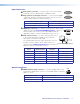
The three buttons with corresponding LEDs on the front panel (labeled Mode, Normal, and
Auto) are used to manually select inputs 1 through 3 or enable and disable device modes
(see the table below). The LEDs indicate status and the currently selected input.
The front panel operations can also be performed remotely with SIS commands (see SIS
Configuration and Control on page 13) or the FOX Extenders Control Program (see FOX
Extenders Control Program on page 21).
Initial Power Up
Upon initial power up, all the front panel LEDs blink simultaneously. They blink once for
multimode or twice for singlemode. Afterwards, the LEDs return to their normal signal
presence indication.
If a different fiber optic SFP module or no SFP module is connected, the LEDs first blink
once or twice to identify the device, but then blink continuously.