
User guide


FOX T USW 203 Universal Switcher • Installation 6
F
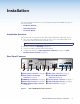
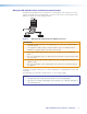
Fiber optic connector — For one-way video, audio, and serial communication from
the FOX T USW 203 to a receiver, connect a fiber optic cable between the Tx port on
the FOX T USW 203 and the Rx port on a compatible receiver.
To return serial data from a receiver to the FOX T USW 203 or for HDCP compliance,
connect a fiber optic cable between the Rx port on the FOX T USW 203 and the Tx port
on the receiver.
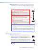
WARNING: Potential risk of severe injury. The
FOX T USW 203 outputs continuous invisible light, which may
be harmful to the eyes; use with caution.
AVERTISSEMENT: Risque potentiel de blessure grave ou
de mort. Le FOX T USW 203 émet une lumière invisible en
continu qui peut être dangereux pour les yeux, à utiliser avec
précaution.
• Do not look into the rear panel fiber optic cable connectors
or into the fiber optic cables themselves.
• Ne regardez pas dans les connecteurs de câble fibre
optique sur le panneau arrière ou dans les câbles fibre
optique eux-mêmes.
• Plug the attached dust caps into the optical transceivers
when the fiber cable is unplugged.
• Branchez les protections contre la poussière dans
l’ensemble émetteur/récepteur lorsque le câble fibre optique
est débranché.
NOTES:
• Ensure that you use the proper fiber optic cable. Typically, singlemode fiber
optic cable has a yellow jacket and multimode fiber optic cable has an orange
or aqua jacket.
• Only one fiber optic cable, transmitter-Tx-to-receiver-Rx, is required for video,
audio, and serial command transmission, but the HDMI signal output on the
receiver will not be HDCP-compliant and the FOX T USW 203 will not receive
RS-232 reports from the controlled device.
The Link LED indicators light when there is light presence on either fiber optic port.
RS-232 Over Fiber and Alarm Connector
G
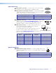
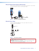
RS-232 Over Fiber connector — To pass serial command signals to
a receiver (for serial control of a projector, for example), connect a host
device to the transmitter via the leftmost poles (Tx, Rx, and G) of this
5-pole captive screw connector (see Wiring for RS-232 Over Fiber and
Alarm Communication on page 8 for wiring configurations).
Alarm connector — For remote monitoring of the status of fiber optic
link 2, connect a custom or furnished monitoring device to the switcher via
the rightmost poles (1 and 2) of this 5-pole captive screw connector (see
Wiring for RS-232 Over Fiber and Alarm Communication on page 8).
NOTE: Pins 1 and 2 short within the switcher when link 2 does not detect any
connection.
Tr
ansmitter
to
Receiver
OPTICAL
Rx
Tx
LINK
LINK
OPTICAL
Rx
Tx
LINK
LINK
ALARM
Tx Rx G 1 2
RS-232
OVER FIBER
ALARM
Tx Rx G 1 2
RS-232
OVER FIBER