
User guide


FOX T USW 203 Universal Switcher • Installation 5
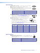
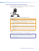
Input Connectors
A
Analog video connector — Connect a video source to the female
15-pin HD connector, labeled input 1 or RGB/R-Y, Y, B-Y.
B
Analog video loop-through connector — Connect an analog RGB
or YUV video display to the female 15 HD VGA connector for a local
display of input 1 (VGA). This output is always on.
Selected Video Input VGA Loop-thru Output
VGA (input 1) Always on
HDMI (inputs 2 and 3) N/A
C
HDMI input connectors — Connect a source device to either or both
HDMI connectors (see Connecting HDMI Connectors on page 7).
These are inputs 2 and 3. They can accept HDMI DVI (with an
appropriate adaptor), or dual mode DisplayPort video sources.
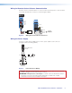
D
Audio input connector — Connect an analog audio source
to the 3.5 mm tip-ring-sleeve (TRS) connector. All three
video inputs can share this audio input.
The following table shows the audio format that is sent over
the fiber connection when a specific audio format is not
specified (see the Audio input selection SIS commands on
page 16 to switch the active audio source).
Selected Video
Input
HDMI Embedded
Audio Present
Analog Audio
Present
Audio Sent Over Fiber
VGA N/A Yes Analog audio
VGA N/A No No audio
HDMI Yes No HDMI embedded audio
HDMI Yes Yes HDMI embedded audio
HDMI No Yes Analog audio
HDMI No No No audio
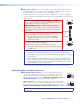
Output Connectors
E
HDMI switched output connector — Connect a display device to the
female type A HDMI output connector for local HDMI output for switched
inputs 1, 2, and 3.
Selected Video Input HDMI Switched Output
VGA (input 1) On (no embedded audio or HDCP compliance)
HDMI (input 2 and 3) On
1
RGB/R-Y, Y, B-Y
LOOP-THRU
HDMI
2
3
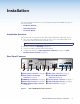
Sleeve ( )
Ring (
-
)
Tip (+)
3.5 mm Stereo Plug Connector
(unbalanced)
HDMI