User Guide Fiber Optic Switcher FOX T USW 203 Three Input Universal Switcher with an Integrated Fiber Optic Transmitter 68-2226-01 Rev.
Safety Instructions Safety Instructions • English WARNING: This symbol, , when used on the product, is intended to alert the user of the presence of uninsulated dangerous voltage within the product’s enclosure that may present a risk of electric shock. ATTENTION: This symbol, , when used on the product, is intended to alert the user of important operating and maintenance (servicing) instructions in the literature provided with the equipment.
FCC Class A Notice This equipment has been tested and found to comply with the limits for a Class A digital device, pursuant to part 15 of the FCC rules. The Class A limits provide reasonable protection against harmful interference when the equipment is operated in a commercial environment. This equipment generates, uses, and can radiate radio frequency energy and, if not installed and used in accordance with the instruction manual, may cause harmful interference to radio communications.
FDA/IEC 60825-1 Requirements CLASS 1 LASER PRODUCT Complies with FDA performance standards for laser products except for deviations pursuant to Laser Notice No. 5, dated June 24, 2007. The product is intended to be used with the fiber optic cables fully installed. This product meets the applicable requirements of IEC 60825-1, Edition 1 (2007). Any service to this product must be carried out by Extron Electronics and its qualified service personnel.
Conventions Used in this Guide Notifications The following notifications are used in this guide: WARNING: Potential risk of severe injury or death. AVERTISSEMENT: Risque potentiel de blessure grave ou de mort. ATTENTION: • Risk of property damage. • Risque de dommages matériels. NOTE: A note draws attention to important information. TIP: A tip provides a suggestion to make working with the application easier.
Contents Introduction............................................................ 1 SIS Configuration and Control......................... 13 About this Guide.................................................. 1 About the FOX T USW 203 Universal Switcher.... 1 System Compatibility....................................... 2 Cable Transmission Modes.............................. 2 Key Features....................................................... 2 Simple Instruction Set Control...........................
FOX T USW 203 Universal Switcher • Contents viii
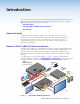
Introduction This section contains general information about this guide and the FOX T USW 203 Universal Switcher with an integrated fiber optic transmitter, selected device features, and a typical application diagram.
WARNING: Potential risk of severe injury. The FOX T USW 203 outputs continuous invisible light, which may be harmful to the eyes; use with caution. AVERTISSEMENT: Risque potentiel de blessure grave ou de mort. Le FOX T USW 203 émet une lumière invisible en continu qui peut être dangereux pour les yeux, à utiliser avec précaution. • Do not look into the rear panel fiber optic cable connectors or into the fiber optic cables themselves.
All digital technology — Delivers pixel-for-pixel transmission of video signals to ensure optimal image quality at resolutions up to 1920x1200 and 2K, including HDTV 1080p @ 60 Hz. Digital conversion of analog video and audio input signals — Digitizes analog signals, ensuring that a reliable, high quality digital video signal is sent to the output destination. Auto-input switching — Automatically switches to the highest or lowest priority input with an active video signal for simplified operation.
Installation This section describes information for connecting and wiring the FOX T USW 203. Topics in this section include: • Installation Overview • Rear Panel Features • Connection Details Installation Overview Follow these steps to install and set up an Extron FOX T USW 203 in a fiber optic system: 1. Turn off all of the equipment. Ensure that the video sources and output display are all turned off and disconnected from the power source.
Input Connectors 1 A Analog video connector — Connect a video source to the female 15-pin HD connector, labeled input 1 or RGB/R-Y, Y, B-Y. B Analog video loop-through connector — Connect an analog RGB or YUV video display to the female 15 HD VGA connector for a local display of input 1 (VGA). This output is always on.
F Fiber optic connector — For one-way video, audio, and serial communication from the FOX T USW 203 to a receiver, connect a fiber optic cable between the Tx port on the FOX T USW 203 and the Rx port on a compatible receiver. To return serial data from a receiver to the FOX T USW 203 or for HDCP compliance, connect a fiber optic cable between the Rx port on the FOX T USW 203 and the Tx port on the receiver.
Control Connectors H I Contact closure connector — Connect a contact closure device (such as a simple switch) to the 3.5 mm, 4-pole captive screw connector. The first three ports are used for selecting inputs 1 through 3 when momentarily shorted to the ground pin (see Wiring for Remote Contact Closure Communication on page 9). CONTACT 1 Remote RS-232 connector — Connect a host device to the 3.5 mm, 3-pole captive screw connector for serial control of the switcher.
Wiring for RS-232 Over Fiber and Alarm Communication The RS-232 Over Fiber port is for transmission of serial signals, such as projector control signals. The alarm port is an internal relay to connect or disconnect a custom alarm circuit. Wire the connector as shown in figure 3 below. RS-232 OVER FIBER ALARM Tx Rx G Tx Rx G 2 1 RS-232 Device Figure 3. 1 2 Alarm Device Wiring the RS-232 Over Fiber and Alarm Connector ATTENTION: • The length of exposed wires in the stripping process is critical.
Wiring for Remote Contact Closure Communication Each port senses an external switch or contact closure. Use these ports to select an input on the switcher. Wire the connector as shown in figure 4 below. CONTACT 1 2 3 G Heat Shrink Over Shield Wires Ground Wire Nut Device 3 G 3 2 1 Figure 4. Switch Device 2 (Switches, relays, or similar items) Device 1 Wiring the Contact Closure Connector Wiring the Power Supply Connect a 12 VDC power supply to the 3.
ATTENTION: • This product is intended to be supplied by a UL Listed Power Unit marked “Class 2” or “LPS,” rated 12 VDC, 1.0 A minimum. Always use a power supply supplied by or specified by Extron. Use of an unauthorized power supply voids all regulatory compliance certification and may cause damage to the supply and the unit. • Ce produit est destiné à une utilisation avec une source d’alimentation listée UL avec l’appellation « Classe 2 » ou « LPS » et normée 12 Vcc, 1,0 A minimum.
Operation This section describes the front panel features of the FOX T USW 203 and describes front panel operations. Topics in this section include: • Front Panel Features • Front Panel Operation Front Panel Features AUTO SWITCH 1 2 3 1 STATUS 2 3 SIGNAL CONFIG HDCP MODE NORMAL AUTO FOX T USW 203 FOX UNIVERSAL SWITCHER A Figure 6. B C D FOX T USW 203 Front Panel Features A B C Auto Switch LED indicator — Lights when the transmitter is in auto switch mode.
Selecting an Input To select an input from the front panel, perform the following actions: 1. Press the input selection button that corresponds with the desired rear panel input connector. 2. The corresponding LED lights to indicate the active input. Setting the Front Panel Lockout Mode (Executive Mode) Push and hold (for about 5 seconds) inputs 1, 2, and 3 simultaneously until the front panel LEDs blink three times to enable or disable front panel configuration.
SIS Configuration and Control This section describes remote control of the FOX T USW 203 through SIS commands and basic installation instructions for the FOX Extenders Control Program (refer to the FOX Extenders Control Program Help File for operation details). To enable serial control of the FOX T USW 203, use a computer running the HyperTerminal or DataViewer utility, or a control system to make serial control of the transmitter.
Error Responses When the FOX T USW 203 receives an SIS command and determines that it is valid, it performs the command and sends the corresponding response to the host device. If the command is determined invalid or contains invalid parameters, the transmitter or receiver returns an error response to the host.
X2& = EDID output resolution and refresh rate See the tables below VGA - PC SIS Value Resolution Refresh Rate (Hz) SIS Value Resolution Refresh Rate (Hz) SIS Value Resolution Refresh Rate (Hz) 1 800x600 60 7 1360x768 60 12 1600x1200 60 2 1024x768 60 8 1366x768 60 13 1680x1050 60 3 1280x720 (analog default) 60 9 1400x1050 60 14 1920x1080 60 4 1280x768 60 10 1440x900 60 15 1920x1200 60 5 1280x800 60 11 1600x900 60 16 2048x1080 60 6 1280x1024 60 SIS
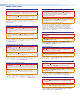
Command and Response Tables for SIS Commands Command ASCII Command (Host to Device) Response (Device to Host) Additional Description Input Switching Commands Input selection NOTE: The FOX T USW 203 saves the last input selection when cycling power. Set video input selection X1! ! In X1! • All] Select input X1!. View video input selection ! X1!] View currently selected source. E 0AUSW } E 1AUSW } Ausw0 ] Switch inputs manually (default).
Command ASCII Command (Host to Device) Response (Device to Host) Additional Description Picture Adjustments Commands (Analog Only) Pixel phase Set a pixel phase value Increment value Decrement value View pixel phase value E 1*X2# PHAS} E 1+PHAS} E 1-PHAS} E 1PHAS} Phas X2#] Adjust the pixel phase to X2#. Phas X2#] Increase the pixel phase. Phas X2#] Decrease the pixel phase X2#] Show the pixel phase value Tpix X2$] Set the total pixels to X2$. Tpix X2$] Increase the total pixels.
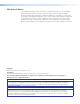
Command ASCII Command (Host to Device) Response (Device to Host) Additional Description EDID Commands NOTE: Digital EDID can be assigned only to a digital input. Analog EDID can be assigned only analog input 1. Input EDID (VGA and HDMI) Assign factory EDID E A X1!*X2& EDID} EdidA X1!*X2&] Set the EDID resolution and refresh for input X1!. View assigned EDID E A X1! EDID} X2&] View EDID resolution and refresh for input X1!.
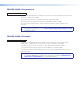
Command ASCII Command Response Additional Description Set front panel executive mode X% X Exe X%] Enable or disable (default) the front panel lockout (executive) mode. View front panel executive mode X X%] View the front panel lockout (executive) mode. Disable Plus mode transmission 81*0# Plus0 ] Disable Plus mode transmission. Enable Plus mode transmission 81*1# Plus1] Enable Plus mode transmission (default). View Plus mode transmission 81# X%] View Plus mode transmission setting.
Command ASCII Command Response Additional Description (Host to Device) (Device to Host) Query general information I 1Lnk X% • 2Lnk X% • Vid X% • Aud X% • X1) • TX ] Query part number N 60-1230-nn] Query firmware version Q x.xx] Query firmware build *Q x.xx.xxxx] Query all firmware version 0Q x.xx.xxxx-x.xx] Query updated FPGA version 35Q x.
FOX Extenders Control Program The Extron FOX Extenders Control Program provides an alternate method to control and configure the FOX T USW 203. The application provides controls to adjust device parameters and manage firmware. The FOX T USW 203 can also be configured and controlled with SIS commands (see SIS Configuration and Control on page 13). The Extron FOX Extenders Control Program communicates with the switcher via the rear panel Remote RS-232 port or front panel USB Config port.
Starting the Software Start the Extron FOX Extenders Control Program as follows: 1. Open the FOX Extenders Control Program. The Communication Setup dialog box appears. Figure 8. Communication Setup Window Connection Methods 2. Select the desired connection method. • To connect the software to the device through the rear panel Remote RS-232 connector, click the RS232 tab and select the desired port from the Port drop-down list (see the left side of figure 8).
Figure 9. Main Screen The main screen consists of a menu bar, Status panel, Input panel, and Configuration panel. Menu Bar The menu bar consists of three menus for connection options, device information and configuration, and additional resources. File menu The File menu contains options for connecting and disconnecting the device and exiting the FOX Extenders Control Program. Figure 10. File Menu NOTE: Options that appear gray are not available.
Connect The Connect option establishes communication with a disconnected device. A disconnected device may include a device that has timed out after prolonged inactivity or a new device that has yet to be connected. If a device is already connected, the Connect option is disabled until the device is disconnected or the connection times out. To establish a connection: 1. From the File menu, select Connect. Alternatively, click the icon below the menu bar.
Unit Info The Unit Info option opens a dialog box with information about the connected device. Figure 12. Unit Info Dialog Box 1. From the Tools menu, select Unit Info. This opens a dialog box displaying information about the connected unit. The displayed information includes: • Model number of the device • Name of the device model • Description of the model • Firmware version currently found on the device • Firmware build • FPGA version 2.
Master System Reset — Resets all unit settings and user settings to factory defaults. From the Tools menu, locate the Reset Unit submenu and select Master System Reset. Figure 14. Unit System Dialog Box Audio Gain/Atten. Reset — Resets the level of audio gain and attenuation to factory defaults. From the Tools menu, expand the Reset Unit submenu and select Audio Gain/Atten. Reset. Figure 15. Audio Gain and Attenuation Reset Dialog Box Presets Reset — Is not available for the FOX T USW 203.
Update Firmware The Update Firmware option opens the Extron Firmware Loader application. This application is used to upload new firmware to the connected device (see Downloading Firmware on page 40 to download new firmware). NOTE: In order for the Update Firmware option to work, install the Firmware Loader application (see Downloading Extron Firmware Loader on page 39). Otherwise, the Update Firmware option is disabled. To update firmware: 1.
Trace Window The Trace Window option displays data sent to and received from the device in a separate window for troubleshooting. Figure 17. Trace Window Dialog Box 1. From the Tools menu, select Trace Window. The Trace Window dialog box opens. 2. To clear existing information, click the Clear button. 3. Click the Close button to close the Trace Window dialog box.
Extron Home Page The Extron Home Page option displays the Extron website. The Extron website contains supporting documentation for Extron products and downloadable firmware and software updates (see Downloading Extron Firmware Loader on page 39). From the Help menu, select Extron Home Page. This opens a new Internet browser window to the Extron website. Check for Updates The Check for Updates option verifies that the latest version of the FOX Extenders Control Program is being used.
Main Screen The main screen contains status information, input selection, and configuration options. Figure 20. Main Screen NOTE: The main screen may appear different from the image above depending on what is connected. Functions which are not applicable are disabled. Status panel Figure 21. Status Panel The Status panel of the screen provides visual indications of the connection status and the names of the connected units.
Video Indicator — Displays green when the transmitter detects an active signal on the VGA input. Audio Indicator — Displays green when the device detects audio with the selected input. If the selected input has an analog audio signal above -44 dBV, the indicator turns green immediately, but turns gray after the audio signal level drops below the threshold continuously for 10 seconds.
VGA Video Adjustment panel The VGA Video Adjustment panel of the Control tab adjusts the following video parameters on the analog input: horizontal start, pixel phase, and total pixels. Figure 24. VGA Video Adjustment Panel Horizontal Start — Defines the number of pixels in the blanking area to the left of the active area. In the Horizontal Start panel of the VGA Video Adjustment panel, click the Left or Right arrows, or click and drag the slider to adjust the setting to the desired value.
Audio Adjustment panel The Audio Adjustment panel of the Control tab allows adjusts the gain and attenuation of analog input audio. Figure 25. Audio Adjustment Panel Audio Gain and Attenuation — Adjusts the analog input audio gain or attenuation value. This ranges from -18.0 dB to +10.0 dB in 1.0 dB increments. In the Audio Gain/Atten. panel, click and drag the slider to the desired level. The current value is displayed in a field below the slider control.
Plus Mode Transmission panel Plus mode can support rates up to 1920x1200 @ 60 Hz and 2K, with embedded audio, and is HDCP compliant. Non-Plus mode supports rates up to 1600x1200 and 1080p, is HDCP compliant, but does not support audio de-embedding (analog audio is still supported). In the Plus Mode Transmission panel, click the Enabled radio button to enable Plus mode. To disable Plus mode, click the Disabled radio button. NOTE: Default setting: Plus Mode is Enabled.
Advanced Configuration panel Executive mode restricts access to the front panel button functions. To enable or disable executive mode, click either the On or Off radio button in the Executive Mode panel. NOTE: Turning on executive mode will not disable the ability to control the device with the FOX Extenders Control Program. EDID Configuration Tab EDID is a data structure used to communicate video display information, including native resolution and vertical refresh rate requirements, to a source device.
Save EDID panel To save EDID from displays that are connected to the VGA Loop-Thru or HDMI Switched Output connector, perform the following: 1. Select VGA Loop-Thru EDID or the desired HDMI Switched Output EDID from the drop-down list. Figure 31. Save EDID Options 2. Click the Save button. The EDID setting is saved. The saved VGA Loop-Thru and HDMI Switched Output EDID can be assigned to a desired input using the Assign EDID function. NOTE: There are 4 available memory locations to save digital EDID.
2. Click on the Browse button to locate and select the desired EDID file on the connected PC. The Open dialog box opens. Figure 34. Browse Button for Importing EDID 3. Select the EDID file and click the Open button. The Open dialog box closes. 4. Click the Import button. The EDID is imported and assigned to the selected input. Export EDID panel EDID files on the FOX T USW 203 can be exported to the connected PC. To open and view them, use the Extron EDID Manager software, available at www.extron.com.
Reference Information This section contains mounting and firmware updating information. Topics in this section include: • Mounting • Updating Firmware Mounting The FOX T USW 203 can be placed on a tabletop or mounted in a rack or underneath a desk. Tabletop Use Attach the provided rubber feet to the bottom four corners of the enclosure. Mounting Kits Mount the unit using any optional compatible mounting kit listed on the Extron website in accordance with the directions included with the kit.
Updating Firmware To update firmware for the FOX T USW 203, download the new firmware to a connected computer and upload the firmware with the Firmware Loader utility or the FOX Extenders Control Program (see to the FOX Extenders Control Program Help File). Downloading Extron Firmware Loader Figure 36. Software Download Page on the Extron Website 1. On the Extron website, click the Download tab (see figure 36, 1). 2. From the left sidebar, click the Software link (see figure 36, 2). Figure 37.
Installing Firmware Loader 1. Once Firmware Loader has been downloaded, run the .exe file from the save location. The installation wizard window opens. 2. Click Next to continue through the process, filling out necessary information and specifying custom settings on each prompt. Downloading Firmware Figure 38. Downloading Firmware from the Extron Website 1. On the Extron website, click the Download tab (1). 2. From the left sidebar, click the Firmware link (2). 3. Navigate to FOX T USW 203. 4.
Installing Firmware with Firmware Loader 1. Open Firmware Loader to establish a connection between the computer and the device. The Add Device... dialog box opens. Figure 39. Add Device... Dialog Box (Connected through USB) 2. Select FOX T USW 203 from the Device Name drop-down list. 3. Select the method of connection from the Connection Method drop-down list. 4. Depending on the connection method, additional options appear. Make the appropriate selections for the current connection method. 5.
Extron Warranty Extron Electronics warrants this product against defects in materials and workmanship for a period of three years from the date of purchase.