User Guide Fiber Optic Extenders FOX RS 104 Four Port Fiber Optic RS-232 Inserter No Photo Available yet 68-2172-01 Rev.
Safety Instructions Safety Instructions • English WARNING: This symbol, , when used on the product, is intended to alert the user of the presence of uninsulated dangerous voltage within the product’s enclosure that may present a risk of electric shock. ATTENTION: This symbol, , when used on the product, is intended to alert the user of important operating and maintenance (servicing) instructions in the literature provided with the equipment.
FCC Class A Notice This equipment has been tested and found to comply with the limits for a Class A digital device, pursuant to part 15 of the FCC rules. The Class A limits provide reasonable protection against harmful interference when the equipment is operated in a commercial environment. This equipment generates, uses, and can radiate radio frequency energy and, if not installed and used in accordance with the instruction manual, may cause harmful interference to radio communications.
Software Commands Commands are written in the fonts shown here: ^AR Merge Scene,,Op1 scene 1,1 ^B 51 ^W^C [01] R 0004 00300 00400 00800 00600 [02] 35 [17] [03] E X! *X1@* X1%* X1&* X! CE} NOTE: For commands and examples of computer or device responses mentioned in this guide, the character “0” is used for the number zero and “O” is the capital letter “o.” Computer responses and directory paths that do not have variables are written in the font shown here: Reply from 208.132.180.
Contents Introduction............................................................ 1 About this Guide.................................................. 1 About the Inserter................................................ 1 Fiber Cable Transmission Modes..................... 3 Features.............................................................. 4 Installation and Operation................................... 5 Rear Panel Connections...................................... 5 Making Connections................
FOX RS 104 RS-232 Inserter • Table of Contents vi
Introduction WARNING: Risk of eye injury: The fiber optic FOX RS 104 RS-232 Inserter outputs continuous invisible light that may be harmful to the eyes; use with caution. • Do not look into the fiber optic cable connectors or into the fiber optic cables themselves. • Plug the attached dust caps into the optical transceivers when the fiber cable is unplugged.
FOXBOX Tx VGA/YUV FOXBOX Tx VGA/YUV FOXBOX Tx VGA/YUV Rx Tx Rx 1 2 Fiber Optic Transmitter Rx LINK LINK RGB/ YUV CONFIG FOXBOX Tx VGA/YUV OPTICAL Extron FOXBOX Tx VGA/YUV RS-232 OVER FIBER ALARM Tx LINK Tx CONFIG AUDIO FOXBOX Tx VGA/YUV 2 OVER TEMP Rx OPTICAL 1 RS-232 RGB/YUV INPUT POWER 12V 1.
Extron FOX Matrix 3200 Modular Fiber Optic Matrix Switcher OUT OUT OUT IN OUT IN OUT IN OUT IN OUT IN OUT IN IN MM R IN SM R IN MM R IN SM R 1-8 IN A B C D E F G H ANAHEIM, CA OUT OUT OUT IN OUT IN OUT IN OUT IN OUT IN OUT IN 9 - 16 IN A OUT 17 - 24 25 - 32 D OUT IN OUT IN D D G OUT IN OUT IN C F E OUT IN B E OUT IN C OUT IN OUT IN G OUT IN E H OUT IN F H OUT IN F OUT IN G PRIMARY POWER SUPPLY H REDUNDANT POWER SUP
Features RS-232 insertion to or extraction from one or more of the fiber optic outputs (or both insertion and extraction) from the Ethernet port— Allows direct insertion of bidirectional serial control data into an optical signal. Standard fiber optic signal architecture — Compatible optical signals are digital signals from 270 Mbps through 4.25 Gbps that are sent and received via fiber optic small form factor pluggable (SFP) modules with LC-type connectors.
Installation and Operation This section details the installation and operation of the FOX RS 104 Inserter, including: • Rear Panel Connections • Operation Rear Panel Connections 4 1 1 1 1 1 2 3 4 2 3 FOX RS 104 100-240V ~ 50/60 Hz Tx Rx Tx Rx Tx Rx Tx Rx Tx Rx Tx Rx Tx Rx Tx Rx LAN RESET A 0.3 A MAX B A B A B A B 1a 1b 1c 1d Figure 3.
û Tx B — For one-way communications from the inserter to a downstream device, which typically can be either a receiver or a transmitter, depending on the application, connect a fiber optic cable to the Tx B LC connector. Connect the free end of this fiber optic cable to the Rx connector on the downstream device.
Making Connections Fiber connection examples The fiber optic cable connections is determined by the installation relative to a matrix switcher. When the inserter is installed on matrix switcher input (see figure 4, below): • SFP transceiver B (a) receives the source optical signal, consisting of video and audio. • The inserter throughputs the RS-232 stream via the LAN port (b) and inserts it into or extracts it from the optical signal stream via the UART and SFP transceiver B (c).
LAN port cabling It is vital that your Ethernet cables be the correct cable type and that they be properly terminated with the correct pinout. Ethernet links use Category (CAT) 5e or CAT 6, unshielded twisted pair (UTP) or shielded twisted pair (STP) cables, terminated with RJ-45 connectors. Ethernet cables are limited to a length of 328 feet (100 m). NOTES: • Do not use standard telephone cables. Telephone cables do not support Ethernet or Fast Ethernet. • Do not stretch or bend cables.
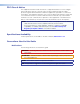
Rear Panel Reset Operations The rear panel Reset button initiates four levels of resets (numbered 1, 3, 4, and 5 for the sake of comparison with an Extron IPL product). The Reset button is recessed, so use a pointed stylus, ballpoint pen, or small screwdriver to access it. See the table on the next page for a summary of the modes. ATTENTION: Review the reset modes carefully. Using the wrong reset mode may result in unintended loss of flash memory programming, port reassignment, or a controller reboot.
NOTE: The reset modes listed below close all open IP and Telnet connections and close all sockets. Also, the following modes are separate functions, not a continuation from mode 1 to mode 5. Reset Mode Comparison and Summary Mode 1 Activation Result Purpose and notes Hold down the recessed Reset button while applying power to the inserter. The inserter reverts to the factory default firmware. Event scripting does not start if the inserter is powered on in this mode.
System Operation After the transmitter, all receivers, the matrix switcher, the inserter, and their connected devices are powered up, the system is fully operational. If any problems are encountered, verify that the cables are routed and connected properly, and that all display devices have identical resolutions and refresh rates. If your problems persist, call the Extron S3 Sales & Technical Support Hotline. See the contact numbers on the last page of this guide for the Extron office nearest you.
Remote Control This section describes the remote control operation of the FOX RS 104, including: • Simple Instruction Set Control • HTML Operation You can use Simple Instruction Set (SIS) commands or built-in HTML pages for operation and configuration of the inserter. You can remotely operate the inserter from a PC connected to the LAN port (item b on page 6). Simple Instruction Set Control Host-to-Unit Instructions SIS commands consist of one or more characters per field.
Using the Command and Response Tables The command and response table begins on page 15. Either uppercase or lowercase letters are acceptable in the command field except where indicated for the audio level (gain and attenuation) commands. Symbols, defined below, are used throughout the table to represent variables in the command and response fields. Command and response examples are shown throughout the table. The ASCII to Hex conversion table below is for use with the command and response table.
X1# X1$ = Number of open connections 0 – 200 = Password 12 alphanumeric characters NOTE: X1% X1^ X1& X1* X1( X2) X2! The HTML language reserves certain characters for specific functions (see “Special Characters” on page 28). = DHCP 0 =off, 1 = on = Baud rate 9600, 19200, 38400, 115200 = Parity odd, even, none, mark, space (Only the first letter required.
Command and Response Table for Inserter SIS Commands Command ASCII Command Response (host to unit) (unit to host) Additional description Enable and disable serial insertion ports Enable one port EX!*1LRPT} LrptX!*1] Enable serial insertion port X! (allow data to be inserted onto fiber optic port X!). Disable serial insertion port X!.
Command ASCII Command Response (host to unit) (unit to host) Additional description Information requests (Continued) Set IP address Read IP address Read hardware address Read # of open connections Set subnet mask Read subnet mask Set gateway IP address Read gateway IP address Set administrator password Read administrator password Reset (clear) administrator password Set user password Read user password Reset (clear) user password Set DHCP on or off Read DHCP on/off status Set serial port parameters E
HTML Operation The inserter can be controlled and operated through its LAN port, connected via a LAN or WAN, using a web browser such as the Microsoft Internet Explorer. The display in the browser of the status or operation of the inserter has the appearance of web pages. This chapter describes the factory-installed HTML pages, which are always available and cannot be erased or overwritten. NOTE: If your Ethernet connection to the inserter is unstable, try turning off the proxy server in your Web browser.
NOTE: A User name entry is not required. 6. Click in the Password field and type in the appropriate administrator or user password. Click the OK button. The inserter checks several possibilities, in the following order, and then responds accordingly: • Does the address include a specific file name, such as 10.13.156.10/.html? If so, the inserter downloads that HTML page. • Is there a file in the inserter memory that is named “index.html”? If so, the inserter downloads “index.
Configuration Tab System Settings page The FOX inserter downloads the System Settings page (see figure 11) when you click the Configuration tab. The screen consists of fields in which you can view and edit IP administration and system settings. You can access the Port Settings, Passwords, and Firmware Upgrade pages by clicking the appropriate link. Refresh Port Settings Passwords Firmware Upgrade Figure 11.
IP Address field — The IP Address field contains the IP address of the connected inserter. This value is encoded in the flash memory of the inserter. Valid IP addresses consist of four 1-, 2-, or 3-digit numeric octets separated by dots (periods). Each field can be numbered from 000 through 255. Leading zeroes, up to 3 digits total per field, are optional. Values of 256 and above are invalid. The factory-installed default address is 192.168.254.
To sync the inserter clock to the connected PC, click the Local Date/Time button and then click the Submit button. NOTE: Use of the Local Date/Time button has no effect on the Zone and Daylight Savings functions. For more complete control of the date and time settings, change the settings as follows: 1. Click the drop box for the desired value. The adjustable variables are month, day, year, hours, minutes, AM/PM, and (time) zone.
RS-232 Port Settings page Access the Port Settings page (see figure 13) by clicking the Port Settings link on the System Settings page. System Settings Refresh Passwords Firmware Upgrade Figure 13. RS-232 Port Settings Page To tailor the serial data output on one of the fiber optic ports, select the radio button for a port and then use the drop-down boxes to select the baud rate, number of data bits, parity, and number of stop bits.
The fields on the Passwords page are for entering and verifying administrator and user passwords. Passwords are case sensitive and are limited to up to 12 uppercase and lowercase alphanumeric characters. Each password must be entered twice; once in the Password field and then again in the Re-enter Password field. Characters in these fields are masked by asterisks (*****). If you do not want to password protect an access level, leave the Password field and the Re-Enter Password field blank.
Downloading the firmware from the website To obtain the latest version of firmware for your FOX inserter: 1. Visit the Extron website, www.extron.com, click the Download tab, and then click the Firmware link on the left sidebar menu (see figure 16). 1 1 Figure 16. Location of Firmware Upgrade Files 2. On the Download Center screen (see figure 17), click the Download link for the appropriate firmware file. 2 Figure 17. Finding Inserter Firmware 3.
4. Follow the instructions on the rest of the download screens to download the firmware update from the Extron website, start the Extron Installation Program to extract the firmware file, and place it in a folder identified in the program window. ATTENTION: The firmware file must have an .s19 extension. Other file types can cause the inserter to stop functioning. NOTES: • When downloaded from the Extron website, the firmware is placed in a subfolder of C:\Program Files\Extron\Firmware.
Uploading the firmware to the inserter Update the firmware on your FOX inserter: 1. Connect the PC to the FOX inserter via the LAN port of the inserter. 2. Access the FOX inserter using HTML pages. 3. Click the Configuration tab (see figure 20). 3 4 5 7 6 7 Figure 20. Firmware Upgrade 4. Click the Firmware Upgrade link. 5. Click the Browse button. An open file window appears. 6. Navigate to the folder where you saved the firmware upgrade file and select it. 7. Click the Open button. 8.
File Management Tab File Management page To delete files such as user-supplied HTML pages from the inserter or to upload your own files to the inserter, click the File Management tab. The inserter downloads the file management HTML page (see figure 21). Figure 21. File Management Page NOTE: The files listed in figure 21 are shown for example only and may not be present on your inserter. To delete a file, check the associated delete check box and click the Delete Files button.
Special Characters The HTML language reserves certain characters for specific functions. The inserter does not accept these characters as part of preset names, name of the inserter, passwords, or locally created file names. The inserter rejects the following characters: {space (spaces are ok for names)} + ~ , @ = ‘ [ ] { } < > ’ “ semicolon (;) colon (:) | \ and ?.
Reference Information This section discusses the specifications, part numbers, and accessories for the FOX RS 104 Inserter.
Cables Fiber cable assemblies Cable Part Number 4LC MM LC to LC Multimode Fiber Optic Cable Assemblies 26-652-nn 2LC OM4 MM P LC to LC Laser-Optimized Multimode Fiber Optic Cable Assemblies — Plenum 26-671-nn 2LC SM P LC to LC Bend-Insensitive Singlemode Fiber Optic Cable Assemblies — Plenum 26-670-nn Bulk fiber cable and termination tools Cable or tool Part Number OM4 MM P/2K Plenum 2 km (6,562 foot) Spool 22-225-02 SM P/2K Plenum 2 km (6,562 foot) Spool 22-223-02 Fiber Optic Termination Kit
Mounting the Inserter ATTENTION: Installation and service must be performed by authorized personnel only. The 1-inch high, half rack width FOX RS 104 Inserter can be placed on a table or mounted in a rack. Tabletop Use Affix the included rubber feet to the bottom of the unit and place it in any convenient location. Mounting Kits Mount the unit using any of the mounting kits listed on page 29, in accordance with the directions included with the kit.
Extron Warranty Extron Electronics warrants this product against defects in materials and workmanship for a period of three years from the date of purchase.