
User Guide User guide

FOX II DP Transmitter and Receiver • Remote Control
30
1
5
2
3
6
7
8
4
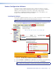
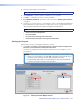
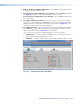
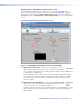
Figure 17. Status Window for the Receiver
Using the Software
Once you have connected to a device, the Status screen (see figure 16, on the previous
page, for the transmitter and figure 17, above, for the receiver) is the default start-up screen
for the Product Configuration Software. The screen provides indications of the connection
status.
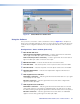
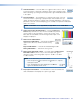
Configuration > Status window (both units)
a Fiber Rx Link indicators
Link 2 indicator (transmitter connection) — Indicates green when the transmitter
detects light on the fiber optic cable connected to the Rx port.
Link 1 indicator (receiver connection) — Indicates green when the receiver detects
light on the fiber optic cable connected to the Tx port.
b Manufacturer fields — Indicates the manufacturer of the SFP module.
c Tx Power fields — Indicates the power on the Tx optical module of the unit in dBm.
d Rx Power fields — Indicates the power on the Rx optical module of the unit in dBm.
e Operating Temperature — Indicates the temperature in degrees Fahrenheit and
degrees Celsius.
f Video Signal Presence indicators
Transmitter connection — Indicates green when the transmitter detects a sync signal
on its DisplayPort video input.
Receiver connection — Indicates green when the receiver detects a digital video
signal on its fiber optic input.
g Audio Signal Presence indicators
Transmitter connection — Indicates green when the transmitter detects a low level
analog audio signal for a short period or embedded audio. This indicator goes dark if
the detected analog audio signal drops below the minimum threshold for a short period.
Receiver connection — Indicates green when the receiver detects an embedded
digital or low level analog audio signal on its fiber optic input.