
User Guide User guide

FOX II DP Transmitter and Receiver • Installation and Operation
13
Audio connections
NOTE: The level of the analog audio inputs can be set via an SIS command (see
page 21) to the transmitter or using the Product Configuration Software (see
page 33).
The following table shows the audio format that is sent over the fiber connection, along with
the DisplayPort video, when a specific audio format is not specified (see the Input audio
selection SIS commands on page 22 to switch the active audio source).
Embedded
DisplayPort Audio
Analog Audio
Transmitted Audio
Present Not present Embedded audio
Present Present Embedded audio
Not present Present Analog audio
Not present Not present No audio
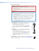
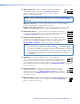
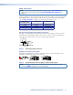
3.5 mm mini jack input and output connections
See figure 7 to identify the tip, ring, and sleeve when you are making connections for the
transmitter from existing audio cables. A mono audio connector consists of the tip and
sleeve. A stereo audio connector consists of the tip, ring, and sleeve.
Sleeve ( )
Ring (
-
)
Tip (+)
3.5 mm Stereo Plug Connector
(balanced)
Figure 7. Stereo Plug Audio Connector
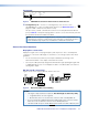
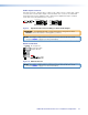
Captive screw input connections
See figure 8 to properly wire a captive screw input connector, either audio input on the
transmitter or return audio input on the receiver.
Unbalanced Stereo Input
Balanced Stereo Input
Do not tin the wires!
Tip
Ring
Tip
Ring
LR
Sleeves
Tip
Sleeve
Sleeve
Tip
LR
Figure 8. Captive Screw Connector Wiring for Stereo Audio Inputs
NOTE: The length of exposed wires is important (see the first two RS-232 and IR
connector NOTES on page 12 for more information).