
User Guide User guide

FOX II DP Transmitter and Receiver • Installation and Operation
11
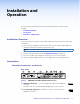
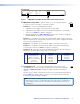
n Audio output ports — These connectors output the transmitted,
LR
AUDIO
unamplified, line level analog audio (see Audio connections on
page 13 to wire these connectors). These connectors output
professional level (+4 dBu) audio.
NOTE: If embedded digital audio is present on the DP connector, these analog
audio connectors do not output audio unless forced using an SIS command (see
page 22).
Mini jack connector — Connect an audio device, such as an audio amplifier or
powered speakers to this 3.5 mm mini jack connector.
Captive screw output connector — Connect an audio device, such as an audio
amplifier or powered speakers to this 5-pole, 3.5 mm captive screw connector.
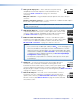
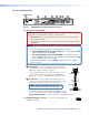
o Audio Return In port — Connect a balanced or unbalanced audio input
LR
AUDIO
RETURN IN
to this 3.5 mm, 5-pole captive screw connector for return to the transmitter
(see Audio connections on page 13 to wire these connectors).
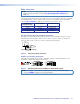
p Bidirectional RS-232 and IR port — Connect a serial RS-232 signal, a
RS-232
IR
Tx Rx Tx RxG
OVER FIBER
modulated or unmodulated IR signal, or both to this 3.5 mm, 5-pole captive
screw connector for bidirectional RS-232 and IR communication (see
RS-232 and IR connections on page 12 to wire the connector).
NOTES:
• If you connect only one fiber optic cable (see item
l
, on the previous page),
you will not receive RS-232 or IR reports from the controlled device. To receive
responses from the controlled device, you must install two fiber optic cables.
• The FOX II DP can pass RS-232 commands and responses at rates up to
115200 baud.
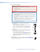
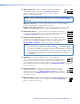
q Alarm port — For remote monitoring of the status of fiber optic
RS-232
ALARM
1 2 Tx RxG
REMOTE
link 2, connect a locally-constructed or furnished monitoring device to the
receiver via the two leftmost poles (1 and 2) of this 5-pole captive screw
connector. When the receiver does not detect a light link on fiber cable Rx,
pin 1 and pin 2 of this port are shorted together. (see Alarm connection on page 13 to
wire this connector).
r Remote RS-232 port — For serial control of the receiver, connect a
RS-232
ALARM
1 2 Tx RxG
REMOTE
host device, such as a computer or touch panel control, via this 3-pole
captive screw connector (see RS-232 and IR connections on page 12 to
wire this connector). See Remote Control on page 18 for SIS commands
and software control.
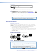
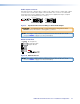
s DC power input — Plug the included external 12 VDC power supply into this
POWER
12V
1.2 A MA
X
connector. The LED indicates power is applied (see Power supply wiring on
page 15, to wire the connector).