
User Guide User guide

FOX II DP Transmitter and Receiver • Installation and Operation
8
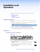
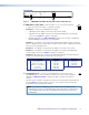
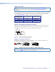
h Fiber optic ports and LEDs —
WARNING: Potential vision damage — These units output continuous laser
light, which may be harmful to the eyes; use with caution.
• Do not look into the rear panel fiber optic cable connectors or into the fiber
optic cables themselves.
• Plug the attached dust caps into the optical transceivers when the fiber cable is
unplugged.
NOTES:
• Ensure that you use the proper fiber cable for your transmitter and receiver
pair. Typically, singlemode fiber has a yellow jacket and multimode cable has an
orange or aqua jacket.
• Only one fiber optic cable, transmitter-Tx-to-receiver-Rx, is required for video,
audio, and serial command transmission. But, if you connect only one fiber
optic cable:
The digital video signal output by the receiver is not HDCP-compliant.
You will not receive RS-232 reports from the controlled device.
To receive responses from the controlled device and for HDCP compliance, you
must install both fiber optic cables.
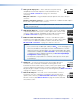
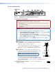
é Tx (required) — For all one-way video, audio, and serial
T
ransmitter
to
Receiver
OPTICAL
Rx
Tx
LINK
LINK
OPTICAL
Rx
Tx
LINK
LINK
8a 8b
communications from the transmitter to the receiver, connect a
fiber optic cable to the Tx LC connector.
Connect the opposite end of this fiber optic cable to the Rx LC
connector on the FOX II DisplayPort receiver (see item
l
on
figure 4 and on page 9) or to any other compatible Extron FOX
device.
è Rx (optional) — For all one-way return video, audio, and serial
communications from the receiver to the transmitter, connect a
fiber optic cable to the Rx LC connector.
Connect the opposite end of this fiber optic cable to the Tx LC
connector on a FOX II R DP receiver (see item
l
on figure 4 and
on page 10) or to any other compatible Extron FOX device.
Tx Link and Rx Link LEDs — When lit, the link is active (light is
sensed).
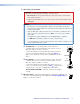
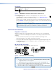
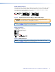
i DC power input — Plug the included external 12 VDC power supply into this
POWER
12V
1.2 A MA
X
connector. The LED indicates power is applied. See Power supply wiring on
page 15, to wire the connector.