
User Guide User guide

FOX II DP Transmitter and Receiver • Installation and Operation
7
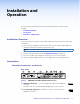
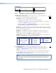
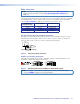
c Analog audio input ports — These connectors accept the analog,
LR
AUDIO
unamplified, line level audio input that can be transmitted to the
receiver (see Audio connections on page 13 to wire these
connectors).
Mini jack connector — Plug an unbalanced audio input into this stereo mini jack
connector.
Captive screw input connector — Connect a balanced or unbalanced audio input to
this 3.5 mm, 5-pole captive screw connector.
NOTE: If both the mini jack and captive screw audio connector are connected, the
mini jack takes priority.
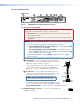
d Audio Return Out port — Connect an audio device, such as an amplifier
LR
AUDIO
RETURN OUT
or powered speakers to this 5-pole, 3.5 mm captive screw connector. This
connector outputs returned, unamplified, line level audio from the receiver.
(see Audio connections on page 13 to wire these connectors).
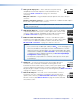
e Bidirectional RS-232 and IR port — Connect a serial RS-232 signal, a
RS-232
IR
Tx Rx Tx RxG
OVER FIBER
modulated or unmodulated IR signal, or both to this 3.5 mm, 5-pole captive
screw connector for bidirectional RS-232 and IR communication. See
RS-232 and IR connections on page 12 to wire the connector.
NOTES:
• If you connect only one fiber optic cable (see item
h
, on the next page), you
will not receive RS-232 or IR reports from the controlled device. To receive
responses from the controlled device, you must install two fiber optic cables
and leave link 2 enabled (via an SIS command to the receiver [see page 25]
or using the Product Configuration Software [see Receiver Input/Output
Configuration screen on page 35]).
• The FOX II DP can pass RS-232 commands and responses at rates up to
115200 baud.
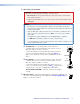
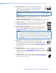
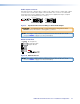
f Alarm port — For remote monitoring of the status of fiber optic link 2,
RS-232
ALARM
1 2 Tx RxG
REMOTE
connect a locally-constructed or furnished monitoring device to the
transmitter via the two leftmost poles (1 and 2) of this 5-pole captive screw
connector. When the transmitter does not detect a light link on fiber cable
Rx (optional), pin 1 and pin 2 of this port are shorted together (see Alarm connection
on page 14 to wire this connector).
g Remote RS-232 port — For serial control of the transmitter, connect a
RS-232
ALARM
1 2 Tx RxG
REMOTE
host device, such as a computer or touch panel control, via this 3-pole
captive screw connector (see RS-232 and IR connections on page 12 to
wire this connector). See Remote Control on page 18 for SIS commands
and software control.