User Guide Fiber Optic Extenders FOX II T DP FOX II R DP Fiber Optic Transmitter and Receiver for DisplayPort 68-1988-01 Rev.
Safety Instructions Safety Instructions • English WARNING: This symbol, , when used on the product, is intended to alert the user of the presence of uninsulated dangerous voltage within the product’s enclosure that may present a risk of electric shock. ATTENTION: This symbol, , when used on the product, is intended to alert the user of important operating and maintenance (servicing) instructions in the literature provided with the equipment.
FCC Class A Notice This equipment has been tested and found to comply with the limits for a Class A digital device, pursuant to part 15 of the FCC rules. The Class A limits provide reasonable protection against harmful interference when the equipment is operated in a commercial environment. This equipment generates, uses, and can radiate radio frequency energy and, if not installed and used in accordance with the instruction manual, may cause harmful interference to radio communications.
Conventions Used in this Guide Notifications The following notifications are used in this guide: WARNING: A warning indicates a situation that has the potential to result in death or severe injury. CAUTION: A caution indicates a situation that may result in minor injury. ATTENTION: Attention indicates a situation that may damage or destroy the product or associated equipment. NOTE: A note draws attention to important information. TIP: A tip provides a suggestion to make working with the application easier.
Contents Introduction............................................................ 1 Remote Control.................................................... 18 About this Guide.................................................. 1 About the FOX II DP Transmitter and Receiver..... 2 Transmitter...................................................... 2 Receiver.......................................................... 2 Both Units....................................................... 2 System Compatibility.........
FOX II DP Transmitter and Receiver • Contents vi
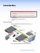
Introduction WARNING: Potential vision damage — The FOX II DP transmitter and receiver output continuous laser light, which may be harmful to the eyes; use with caution. • Do not look into the rear panel fiber optic cable connectors or into the fiber optic cables themselves. • Plug the attached dust caps into the optical transceivers when the fiber cable is unplugged.
About the FOX II DP Transmitter and Receiver The FOX II DP Transmitter and Receiver are an ultra-high performance fiber optic Extender set for long haul transmission of HDCP-compliant DisplayPort video, audio, and RS-232 and IR control signals over fiber optic cabling. The transmitter and receiver can extend DisplayPort signals up to 30 km (18 miles). Transmitter The FOX II T DP transmitter accepts DisplayPort video, at a resolution of up to 2560x1600 and a data rate of up to 10.8 Gbps (2.7 Gbps per lane).
System Compatibility The FOX II T DP transmitter is compatible with all Extron FOX II receivers only. The FOX II R DP receiver is compatible with all FOX II transmitters and with existing FOX 500, FOXBOX, and PowerCage FOX DVI, VGA and HDMI transmitters: • DVI Plus models: Resolutions up to 1920x1200 @ 60 Hz, with embedded audio and analog audio support • Non plus models: Resolutions up to 1600x1200 @ 60 Hz, with analog audio support. Embedded audio is not supported.
Features Ultra high performance — Offers pixel-for-pixel DisplayPort video transmission, up to 2560x1600 at 60 Hz. Video input — The transmitter accepts an input from a DisplayPort source. Loop-through on transmitter — The transmitter has a digital video loop-through on a DisplayPort connector that allows connection of a local monitor.
Simple Instruction Set — The transmitter and receiver use the SIS for easy remote control operation. Upgradable firmware — The firmware that controls the operation of each unit can be upgraded in the field via the USB Configuration port without taking the unit out of service. Firmware upgrades are available for download on the Extron website and they can be installed using the Product Configuration Software.
Installation and Operation This section details the installation of the FOX II DP transmitter and receiver system, including: • Installation Overview • Connections • Indications and Operation Installation Overview Follow these steps to install and set up an Extron FOX II DP transmitter and receiver system for operation: c Turn off all of the equipment. Ensure that the video sources and the output display are all turned off and disconnected from the power source.
c Analog audio input ports — These connectors accept the analog, unamplified, line level audio input that can be transmitted to the receiver (see Audio connections on page 13 to wire these connectors). AUDIO L R Mini jack connector — Plug an unbalanced audio input into this stereo mini jack connector. Captive screw input connector — Connect a balanced or unbalanced audio input to this 3.5 mm, 5-pole captive screw connector.
h Fiber optic ports and LEDs — WARNING: Potential vision damage — These units output continuous laser light, which may be harmful to the eyes; use with caution. • Do not look into the rear panel fiber optic cable connectors or into the fiber optic cables themselves. • Plug the attached dust caps into the optical transceivers when the fiber cable is unplugged. NOTES: • Ensure that you use the proper fiber cable for your transmitter and receiver pair.
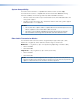
Front panel VIDEO AUDIO EDID SELECT CONFIG SIGNAL INPUT HDCP RETURN OUT 1 2 FOX II T DP 11 Figure 3. j 10 FOX II DP Transmitter Front Panel Control and Connector EDID Select rotary switch — Set this switch to one of the positions below to select the source of the DDC or a specific resolution. EDID SELECT Position 0 — A user-recorded EDID that has been: • Captured from the display connected to the receiver output.
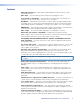
Receiver Connections Rear panel POWER 12V 1.2 A MAX FOX II R DP OUTPUTS 14 AUDIO L DISPLAYPORT Figure 4. l 15 R AUDIO RETURN IN L 17 18 16 R OVER FIBER RS-232 IR Tx Rx G Tx Rx REMOTE RS-232 ALARM 1 2 12 Tx Rx G Tx Rx LINK 13 LINK 19 OPTICAL FOX II DP Receiver Rear Panel Connections Fiber optic ports and LEDs — WARNING: Potential vision damage — These units output continuous laser light, which may be harmful to the eyes; use with caution.
n Audio output ports — These connectors output the transmitted, unamplified, line level analog audio (see Audio connections on page 13 to wire these connectors). These connectors output professional level (+4 dBu) audio. AUDIO L R NOTE: If embedded digital audio is present on the DP connector, these analog audio connectors do not output audio unless forced using an SIS command (see page 22). Mini jack connector — Connect an audio device, such as an audio amplifier or powered speakers to this 3.
Front panel VIDEO CONFIG AUDIO SIGNAL INPUT HDCP RETURN OUT 1 2 FOX II R DP 20 Figure 5. t FOX II DP Receiver Front Panel Controls and Connector Configuration port — Connect a controlling device, such as a PC, to this mini USB B port for control of all FOX II R DP functions (see Remote Control on page 18 for SIS commands and software control).
Audio connections NOTE: The level of the analog audio inputs can be set via an SIS command (see page 21) to the transmitter or using the Product Configuration Software (see page 33). The following table shows the audio format that is sent over the fiber connection, along with the DisplayPort video, when a specific audio format is not specified (see the Input audio selection SIS commands on page 22 to switch the active audio source).
Audio output connector See figure 9, below, to properly wire a captive screw output connector, either audio output on the receiver or return audio output on the transmitter. The connector is included with transmitter, but you must supply the audio cable. Use the supplied tie-wrap to strap the audio cable to the extended tail of the connector. No Ground Here Figure 9.
Power supply wiring ATTENTION: Always use power supplies specified by Extron for the FOX II units. Use of an unauthorized power supply voids all regulatory compliance certification and may cause damage to the supply and the unit. Figure 11 shows how to wire the power connector. Smooth A Ridges A SECTION A–A Power Supply Output Cord Tie Wrap 3 5 Captive Screw Connector Figure 11.
Indications and Operation Transmitter Indications 1 2 3 VIDEO CONFIG AUDIO SIGNAL INPUT HDCP RETURN OUT Figure 12. FOX II DP Transmitter Front Panel Features a b (power) indicator — Indicates that power is applied to the unit. Video LEDs — Signal LED — Lights when the transmitter detects an active signal on its video input. HDCP LED — Lights when the input signal is HDCP encrypted.
Operation After the transmitter, all receivers, and their connected devices are powered up, the system is fully operational. If any problems are encountered, verify that the cables are routed and connected properly, and that all display devices have identical resolutions and refresh rates. If your problems persist, call the Extron S3 Sales & Technical Support Hotline. See the contact numbers on the last page of this guide for the Extron office nearest you.
Remote Control This section describes the remote control operation of the FOX II DP transmitter and receiver, including: • Simple Instruction Set Control • Product Configuration Software The transmitter and receiver each have a front panel Configuration port, a mini USB jack (see item k on page 9 and item t on page 12) and a rear panel Remote RS-232 port, a 3-pole captive screw connector (see RS-232 and IR connections on page 12).
Unit-initiated Messages When a local event, such as an equipment power-up, occurs, the unit responds by sending a message to the host. The unit-initiated messages are listed below: (c) Copyright 20nn, Extron Electronics FOX II T DP, Vx.xx, 60-nnnn-xx]] - or (c) Copyright 20nn, Extron Electronics FOX II R DP, Vx.xx, 60-nnnn-xx]] The connected unit issues the appropriate copyright message (above) when it first powers on. Vx.
Using the Command and Response Tables The command and response table for the transmitter begins on the next page. The command and response table for the receiver begins on page 24. Uppercase and lower case letters are acceptable in the command field except where indicated for the audio level (gain and attenuation) commands. Symbols throughout the table represent variables in the command and response fields. Examples are shown throughout the tables.
Command and Response Table for Transmitter SIS Commands Command SIS Command Response (host to unit) (unit to host) Additional description Set the EDID resolution Example: EAX!EDID} EA23EDID} EdidAX!] EdidA23] View the EDID resolution Save an EDID EAEDID} ESX@EDID} EdidSX@] Save the EDID from the X@ connection to the memory location. Vmt1] Vmt2] Vmt0] Mute the video output, display black video. Mute the video and sync outputs. Output video. Video mute status is X#.
Command/response table for Transmitter SIS commands (continued) Command SIS Command Response (host to unit) (unit to host) Additional description Video shutdown delay NOTES: • The Set Video Delay command blanks the digital video for a specified time to help sink devices correctly detect an AV rate change. • Only video is blanked; embedded audio is not muted. Set delay Example: 3*X&# 3*3# DlyX&] Dly3] View delay 3# X&] Delay video by an interval of X&. Delay video by an interval of 0.
Command/response table for Transmitter SIS commands (continued) Command SIS Command Response (host to unit) (unit to host) Additional description 1S 2S 3S 4S 5S X1#] X1#] X1#] X1#] SigIX1#•SigOX1#•HDCPIX1$•HDCPOX1%] Status requests View link 1 (Tx-to-Rx) status View link 2 (Rx-to-Tx) status View input video status View input audio status View all signal status Report the status of the DisplayPort input, DisplayPort output, HDCP encoding on the input, and HDCP encoding on the output.
Symbol Definitions for Receiver SIS Commands ] } = CR/LF (carriage return/line feed) = Carriage return (no line feed) | = Pipe (can be used interchangeably with the } character) • = Space (hard) character E = Escape key (hex 1B) W = Can be used interchangeably with the E character X# = Video and sync mute status 0 = off 1 = video mute on X$ X% X^ X& 2 = video and sync mute on = Audio gain adjustment range 00 to 10 = Audio level adjustment range –18 to +10 (in 1.
Command/response table for Receiver SIS commands (continued) Command SIS Command Response (host to unit) (unit to host) Additional description Audio input gain and attenuation (for analog audio return) NOTE: The set gain (G) and set attenuation (g) commands are case sensitive. The increment level, decrement level, and show level are not case sensitive.
Command/response table for Receiver SIS commands (continued) Command SIS Command Response (host to unit) (unit to host) Reset audio EZA} Zpa] System reset EZXXX} Zpx] Additional description Resets Reset the audio output to the consumer level and return audio gain and attenuation to 0 dB. Reset all settings to factory defaults.
Product Configuration Software The Extron Product Configuration Software, which communicates with the connected transmitter or receiver via the rear panel Remote RS-232 port or front panel Configuration USB port of that unit, provides an easy way to operate and configure the unit. The program is compatible with Windows 2000, Windows XP, or later. Updates to this program can be downloaded from the Extron website. Installing the Software The Product Configuration Software, version 1.
4. Enter the requested personal information; TIP: Click Remember Me to eliminate step 4 in future downloads. 5. Click Download to copy the software or firmware to your computer. 6. Cick Run to confirm that you want to run the installation. 7. For a firmware download, exit this procedure and return to Updating the Firmware on page 37. 8. Follow the on-screen instructions.
2. If this is the first use with the FOX II units, click the New tab. The program opens to the Select Connection Options screen. 3. If necessary for a Remote RS-232 port connection, select the RS232 radio button (see figure 15, item a on on the previous page). Proceed to step 4. If necessary for a Configuration port connection, select the USB radio button (b). Proceed to step 5. 4. For a Remote RS-232 connection, select the Com port to which your transmitter or receiver is connected (c). Click Connect (e).
1 2 3 4 5 Figure 17. 6 7 8 Status Window for the Receiver Using the Software Once you have connected to a device, the Status screen (see figure 16, on the previous page, for the transmitter and figure 17, above, for the receiver) is the default start-up screen for the Product Configuration Software. The screen provides indications of the connection status.
h HDCP Signal indicator — Shows a lock icon ( ) when the digital video signal has a copyright encryption applied and shows an unlocked icon ( ) when the signal is not copyright protected. Configuration > Status screen (transmitter connection only) 9 i 10 Default Active Pixels and Lines fields — These fields display the size (resolution) of the connected DisplayPort video source.
Configuration > EDID Minder screen (transmitter connection only) The EDID Minder screen (see figure 18, below) provides controls for you to tailor the EDID that is provided to the transmitter. Select this screen by clicking the EDID Minder subtab from either the Status or Input/Output Configuration screen or Configuration > EDID Minder from one of the Hardware screens.
Configuration > Input/Output Configuration screen The Input/Output Configuration screen allows you to set the input and output option features of the transmitter (see figure 19, below) and receiver (see figure 20, on page 35). Select this screen by clicking the Input/Output Config subtab from either the Status or EDID Minder screen or Configuration > Input/Output Config from one of the Hardware screen. Transmitter Input/Output Configuration screen 1 6 2 3 4 8 7 5 Figure 19.
c Video Mute button — Click this button to toggle the video mute on and off d Sync Mute button — Click this button to toggle the video mute on and off for the transmitter Loop-through output port. Video mute sends black video while maintaining sync timings from the input video signal. Embedded audio continues to be output. for the transmitter Loop-through output port.
Receiver Input/Output Configuration screen 6 1 7 2 3 4 5 Figure 20. Input/Output Configuration Screen for the Receiver a HDCP Notification radio buttons — Select either the Green or Black b Video Shutdown Delay drop-down box — Click the Video Shutdown Delay drop-down box to set the video shut down delay. This setting radio button to select how the receiver displays HDCP notification on a monitor connected to its DisplayPort Output port.
e Tx Output radio buttons — Select among the available radio buttons to define the function of the receiver Tx LC connector; either: Enable Fiber Out — Routing RS-232 over fiber to the transmitter Disable Fiber Out — No function NOTE: The disable fiber out function is primarily used and recommended when the transmitted signal is routed via a FOX 500 DA6 and the receiver is connected to any of outputs 2 through 6 on the FOX DA.
Hardware > Device Name screen (both units) The Device Name screen provides controls to allow you to assign a locally-assigned name to the unit or to reset the unit to the default name. Select this screen by clicking the Device Name subtab from either the Unit Information or Reset Device screen or Hardware > Device Name from one of the Configuration screens. The Apply and Cancel buttons become selectable when you have entered a name in the Enter a device name: field.
2 2 3 Folder Where Firmware is Installed. 4 Figure 22.
6. Start the Product Configuration Software and connect to the unit (see Starting the Program, steps 1, 2, 3, and 5, starting on page 28. 7. Click Tools > Update firmware. The software asks you to confirm that you want to disconnect it from the unit (see figure 23). 8. Click Continue. The Product Configuration Software disconnects itself from the unit and calls the Firmware Loader utility in the background. The Update Firmware dialog box appears. 8 9 10 10 11 Figure 23. Updating Firmware 9.
11. Click Update. The software advises you that you are about to reprogram the unit firmware. Click OK to continue. The Firmware Loader utility tests the connection, installs the update, and then verifies the firmware. At the conclusion of the process, the utility reports Upload Complete. 12. Click Close. The Product Configuration Software window returns to the front. 13.
Unit Mounting Mounting the Units ATTENTION: Installation and service must be performed by authorized personnel only. Either of the 1-inch high, half-rack width units can be placed on a tabletop or mounted on a rack shelf, or under or through a desk or other furniture. The receiver can be mounted to a projector bracket. Tabletop Use Affix the included rubber feet to the bottom of the unit and place it in any convenient location.
Extron Warranty Extron Electronics warrants this product against defects in materials and workmanship for a period of three years from the date of purchase.