DVS 304 Digital Video Scaler Series DVS 304, DVS 304 D, DVS 304 A , DVS 304 AD 68-1039-01 Rev.
Precautions Safety Instructions • English This symbol is intended to alert the user of important operating and maintenance (servicing) instructions in the literature provided with the equipment. This symbol is intended to alert the user of the presence of uninsulated dangerous voltage within the product’s enclosure that may present a risk of electric shock. Caution Read Instructions • Read and understand all safety and operating instructions before using the equipment.
Quick Start — DVS 304 FCC Class A Notice This equipment has been tested and found to comply with the limits for a Class A digital device, pursuant to part 15 of the FCC Rules. Operation is subject to the following two conditions: (1) this device may not cause harmful interference, and (2) this device must accept any interference received, including interference that may cause undesired operation.
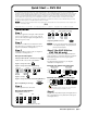
Quick Start — DVS 304, cont’d Step 7 Use the front panel controls and LCD menu screens (shown in Appendix A) or RS-232 programming to configure the scaler. See chapter 2, “Installation and Operation” for more detailed operating procedures, chapter 3, “Serial Communication” for programming information, and chapter 4, “Ethernet Control” for details on the default Web pages. DVD Player Laptop Computer DVS 304 100-240V .
Table of Contents Chapter One • Introduction . ..................................................................................................... 1-1 About this Manual ..................................................................................................................... 1-2 About the DVS 304, DVS 304 A, DVS 304 D, and DVS 304 AD ......................... 1-2 Controlling the DVS 304 video and RGB scaler ..................................................................... 1-2 Features ....
Table of Contents, cont’d RGB Delay ........................................................................................................................... 2-19 OSD label ............................................................................................................................ 2-19 Test pattern ......................................................................................................................... 2-19 Enhance mode ......................................................
Chapter Four • Ethernet Control ......................................................................................... 4-1 Accessing and Using the Web Server . ............................................................................ 4-2 Navigating the Default Web Pages . ................................................................................ 4-3 Status ..........................................................................................................................................
PRELIMINARY Table of Contents, cont’d TOC-iv DVS 304 • Table of Contents
DVS 304 1 Chapter One Introduction About this Manual About the DVS 304, DVS 304 D, DVS 304 A, DVS 304 AD
Introduction About this Manual This manual discusses how to install, configure, and operate the Extron DVS 304 video and RGB scaler and how to operate the optional IR 902 infrared remote control (part #70-495-01). Throughout this manual the terms “DVS”, “digital video scaler”, and “scaler” are used interchangeably to refer to the same product. All instances refer to all models in the series unless noted otherwise.
S-video or composite video signal. RGB and video scaling — Provides a high performance scaling engine with the capacity to scale standard definition video, high definition video, and computer-video signals up or down in resolution. Picture Control — Allows size, position, brightness, contrast, color, tint, detail, zoom and pan adjustments for each input.
Introduction, cont’d Options and accessories The DVS 304’s optional equipment includes: 1-4 • IR 902 remote control — Extron’s IR 902 (part #70-495-01) is an infrared remote control which replicates most of the front panel controls of the DVS 304 (except the Menu and Next buttons). • SDI input card — Serial digital interface (SDI) input can be added to the DVS 304 model by the installation of an SDI input card (part #70-168-01).
DVS 304 2 Chapter Two Installation and Operation Mounting the Scaler Rear Panel Features Front Panel Features Menus, Configuration, and Adjustments Resetting an Input Resetting the Unit System Reset Front Panel Lockout (Executive Mode) IR 902 Infrared Remote Control Setting up the DVS to work with a Matrix Switcher
Installation and Operation Mounting the Scaler The DVS 304 is 1U high, half rack wide, and is rack mountable. Alternatively, it can be placed on a table or other furniture. Rubber feet and rack mounting hardware are included. The 1U high and full rack DVS 304 A (audio model) can be rack mounted using included rack/through-desk mounting brackets. Tabletop/desktop placement Four self-adhesive rubber feet are included with the DVS 304.
Rack mounting the DVS 304 1. If feet were installed on the bottom of the DVS 304, remove them. 2. Place the DVS 304 on one half of the 1U (one unit high, one unit wide) rack shelf (part #60-190-01). Align the front of the DVS 304 with the front of the shelf, and align the threaded holes on the bottom of the DVS 304 with the holes in the rack shelf. 3. Attach the DVS 304 to the rack shelf with the two provided 4-40 x 1/16" machine screws.
Installation and Operation, cont’d Rack mounting the DVS 304 A To mount the DVS 304 A in a rack, do the following: 1. If feet were installed on the bottom of the DVS 304, remove them. 2. Attach the included rack/through-desk mounting brackets (part #70-077-03) to the unit using eight machine screws supplied with the mounting kit. Rack Mount Bracket Figure 2-2 — Attach the mounting brackets and install in rack 3.
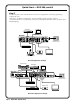
Application diagram The diagram shown below is an example of a typical DVS 304 AD application with cable connections. Digital Tape Deck w/ SDI Output RS-232 Control TCP/IP Network Sound System 2 RS B /B-Y G /Y R /R-Y Y R/C Y /VID SD D /VI YC -Y/ Y,B -Y, B/R RG O U T P U T -23 N LA T SE RE K LIN AC T V H/ HV 4 I B/ ,B Y,Y -Y R- RG YC I N P U T Y BVID 3 2 1 UT TP R OU L O AU L TS PU L 3 4 DI Projector (RGB) R R IN L .
Installation and Operation, cont’d Rear Panel Features The rear panels of the DVS 304 D and DVS 304 AD models (figures 2-4 and 2-5) contain all of the possible connectors available on the DVS 304 series of scalers. 4a 100-240V .
g Video input 4: RGB/R-Y, Y, B-Y/YC/VID — Connect RGBHV, RGBS, RGsB, RGBcvS, YUVi, YUVp, S-video and composite video through this 15-pin HD connector. See pin configurations below. Signal Input 4 Pin Configuraton 5 RGB/R-Y,Y,B-Y/YC/VID 1 10 6 4 15 Pin 1 Pin 2 Pin 3 Pin 13 Pin 14 R G B H V R G B S R G B R-Y Y B-Y Y C Vid RGBHV RGBS RGsB YUV S-video Video 11 N Equipment following the SCART interconnection standard may be connected to the RGBcvS input cabling configuration.
Installation and Operation, cont’d Pins: Straight-through Cable 12345678 (for connection to a switch, hub, or router) End 1 Side View Insert Twisted Pair Wires Pin 1 2 3 4 5 6 7 8 RJ-45 Connector Wire Color white-orange orange white-green blue white-blue green white-brown brown End 2 Pin 1 2 3 4 5 6 7 8 Wire Color white-orange orange white-green blue white-blue green white-brown brown Crossover Cable (for direct connection to a PC) End 1 Pin 1 2 3 4 5 6 7 8 Wire Color white-orange orange whit
Front Panel Features The front panel buttons, controls, LCD, and infrared sensor are found on all models of the DVS 304 scaler series. The LEDs beside each input button will light green when the button is pressed. DVS 304 DIGITAL VIDEO SCALER ADJUST 1 2 3 4 MENU NEXT IR 1 2 4 3 5 6 7 Figure 2-7 — DVS 304 and DVS 304 A front panel Input selection buttons a Input LEDs — The LED of the selected input lights when pressed. A blinking LED indicates an audio breakaway input (audio models only).
Installation and Operation, cont’d Menus, Configuration, and Adjustments Scaler configuration and adjustments can be performed by using the embedded Web pages and the Windows-based control program (see chapter 3, “Serial Communication” for details) or by using the front panel controls and the menus that are displayed on the DVS 304’s LCD screen. These menus are used primarily when the scaler is first set up.
Default Cycle 2 sec. Power on EXTRON DVS 304 2 sec. 60-736-01 FW version 1.00 2 sec. INPUT 1 COMPOSITE 2 sec. OUTPUT 1024 x 768@60 MENU START AUTO IMAGE ON IN1 MENU INPUT CONFIG MENU PICTURE CONTROL MENU OUTPUT CONFIG MENU AUDIO CONFIG (Audio models only) MENU MEMORY PRESETS MENU IP CONFIG MENU ADVANCED CONFIG MENU MENU TO EXIT MENU PRESS NEXT NEXT Figure 2-9 — Main menus N To return to the default screens, allow the DVS 304 to time-out (after 20 seconds).
Installation and Operation, cont’d Start auto image Auto imaging allows you to “auto size” and “auto center” the selected image to fill the screen. The processor measures the sync frequencies of an incoming video source and uses an internal table to set the active image area, total image area, and the sampling frequency. If an unknown input is connected to the DVS 304, the processor measures and estimates the resolution of the incoming video.
N Only inputs 2 and 4 offer selectable video types. From the Input Configuration menu, pressing the Next key successively displays submenus with the input video types for Inputs 2 and 4. The SDI input (where applicable) can be assigned to any input from the Input Configuration menu. Input 1 video type Input 1 can only input composite video, no other video types are selectable for this input.
Installation and Operation, cont’d Picture control The Picture Control menu includes all of the picture settings for the scaler including positioning, sizing (horizontal and vertical control), brightness and contrast, color saturation, tint, detail (sharpness of the picture), and zooming (see figure 2-12). The pan feature is only available when zoom is over 100%. Color, tint and pan controls are available to applicable signals only.
Resolution and refresh rates Rotate the Adjust horizontal ([) knob while in this submenu to select one of the available combinations of output resolutions and refresh (vertical scanning) rates. Rotate the Adjust vertical ({) knob while in this submenu to select one of the available refresh rates. The default resolution and rate for the DVS 304 is 1024 x 768 @ 60Hz.
Installation and Operation, cont’d Audio configuration (DVS 304 A and DVS 304 AD only) Audio Configuration allows the input level to be adjusted between –15 dB to +9 dB for each audio input. OUTPUT CONFIG MENU AUDIO CONFIG NEXT IN1 LEVEL 0dB NEXT (audio models only) Input level Adjust the input gain/attenuation from -15dB to +9dB of the selected input. Figure 2-14 — Audio configuration menu Volume control is available through SIS commands or IR remote control.
Clear (CLR) memory preset From this submenu, up to three saved presets for the currently selected input can be cleared from memory. Using either the Adjust horizontal ([) or Adjust vertical ({) knob, select (< >) either N/A, 1, 2, or 3 to select a preset. The default is . 1. 2. To clear the preset, press the Next button. N Clearing a preset by pressing the Next button will also cause a return to the Memory Preset menu. To exit the Clear memory preset function without clearing a preset, press Menu.
Installation and Operation, cont’d Advanced configuration The following flowchart provides an overview of the Advanced Configuration submenus and the options for each setting. IP CONFIG MENU ADVANCED CONFIG NEXT AUTO IMAGE ON BLUE MODE ON NEXT Auto imaging When auto image is on, the unit automatically sizes and centers each new input. NEXT AUTO MEMORY ON NEXT Auto Memory When set to on, the unit automatically saves the input and picture control settings for inputs 2 and 4.
RGB Delay The RGB delay feature applies a brief delay before displaying a new picture to a screen and allows the display device to adjust to the new sync timing. This feature provides “no-glitch” switching. The blanking period can be set from 0 to 5 seconds in 0.5 second steps. OSD label Use the On-Screen Display (OSD) label menu to determine the time allotment for an input label or a user defined OSD label. Input labels are generic labels shown for inputs 1, 2 and 3.
Installation and Operation, cont’d Picture-in-picture mode The DVS 304 can display two image sources on the screen simultaneously. Keep in mind that when using the PIP feature, one image source must be low-resolution (composite, S-video, YUVi and RGBcvS) video, while the other must be high resolution (YUVp, RGB scaled) video. If these conditions are not met (i.e., two low resolution video inputs or two high resolution inputs are selected), the PIP mode will quit.
Using the swap feature Use the swap feature to switch the active main window input with the current PIP input. For example if the main window is Input 4 (RGB scaled) and the PIP window is Input 1 (composite), applying the swap command results in Input 1 becoming the main window and Input 4 the PIP window. For audio models (DVS 304 A or AD), you can allow audio to follow the main (default) or PIP window.
Installation and Operation, cont’d Resetting the Unit There are four reset modes (numbered 1, 3, 4, and 5) that are available by pressing the Reset button on the rear panel. The Reset button is recessed, so use a pointed stylus, ballpoint pen, or Extron Tweeker to access it. See the following table for a summary of the reset modes. Reset Mode Comparison/Summary Mode Activation Result Purpose/Notes 1 Hold down the recessed Reset button while applying power to the unit.
Front Panel Lockout (Executive mode) To prevent accidental changes to settings, press the Menu and Next buttons simultaneously for 2 seconds to enable the DVS 304’s front panel lockout mode, also known as executive mode. Executive mode locks all front panel functions except input switching and preset recall. The menu system returns to the default menu within 10 seconds. The DVS 304’s front panel is affected by executive mode, but the IR 902 remote is not.
Installation and Operation, cont’d IR 902 Infrared Remote Control The IR 902, shown at right, replicates most of the front panel controls except the Menu and Next buttons. See chapter 3, “Serial Communication”, for details. The topmost part of the IR 902 features memory preset buttons, input switching, picture-in-picture (PIP), volume, and four input selection buttons (1, 2, 3, 4).
Setting up the DVS to work with a Matrix switcher The Sync to Matrix tool is a powerful tool which can simplify the control system necessary when using an Extron Matrix switcher and a DVS 304. The “Sync to Matrix” script can sense when a new tie is made on the matrix is routed to the DVS and automatically recalls the input preset associated with the input on the matrix switcher.
Installation and Operation, cont’d Input 1 Output 1 Input 4 DVS 304 #1 Output to display Input 2 Output 2 Input 4 DVS 304 #2 Output to display Input 3 Output 3 Input 4 Output 4 Input 5 Output 5 Input 4 DVS 304 #6 Output to display Input 6 Matrix Switcher Output 6 (optional) (optional) Output 3 Input 64 Output 4 Figure 2-24 — Multiple DVS 304’s connected to a Matrix switcher 3. On the DVS 304, configure the input as follows: a). Switch to input 4 on the DVS. b).
f). Click Take button to tie the DVS 304’s input to the selected switcher output. The program will create a custom script that will then be loaded onto the DVS 304. The Status box updates with the status of the script on the DVS 304, showing if the DVS 304’s script is connected to the matrix switcher, and showing the current tie associated with output selected. Using the DVS and matrix switcher after the DVS is synchronized to the matrix switcher.
Installation and Operation, cont’d Removing the Sync to Matrix Script If the Sync to Matrix feature is no longer being used, the script can be removed from the DVS by the following steps: 1. Open the Signal Enhancements Windows Control program and connect to the DVS via IP (not RS-232). 2. Under the Tools menu, select Sync DVS 304 to Matrix Switcher... . The Sync DVS 304 to Matrix Switcher window opens. 3. Click Remove Script.
DVS 304 3 Chapter Three Serial Communication SIS™ Programmer’s Guide Control Software for Windows®
Serial Communication The DVS 304 can be remotely controlled via a host computer or other device (such as a control system) attached to the rear panel RS-232 connector or the LAN port. The control device (host) can use either Extron’s Simple Instruction Set (SIS™) commands or the graphical control program for Windows. The scaler uses a protocol of 9600 baud, 1 stop bit, no parity, and no flow control.
Telnet Web Browser Escape (Hex 1B) W [must not be encoded] Carriage Return (Hex 0D) Pipe Character ( ) [must not be encoded] When SIS commands are used through a Web browser, the URL reference is used below to shorten the examples. This would in practice be the full URL of the control interface and Web page reference including all path information. (e.g., http://192.168.254.254/index.
Serial Communication, cont’d Error responses When the DVS 304 receives a valid command, it executes the command and sends a response to the host device. If the unit is unable to execute the command because the command contains invalid parameters, it returns an error response to the host.
Symbol definitions • = Space ] = Carriage return with line feed } = Carriage return with no line feed E = Escape 14, 24, 27, 28 = Superscripts indicate the error message displayed if the command is entered incorrectly or with invalid parameters. See “Error responses”, earlier in this chapter. X! X@ = Specific port number (01-99) = Command data section N For Web encoding only: Data is directed to the specified port and must be encoded if it is non-alphanumeric.
Serial Communication, cont’d X3& = Event buffer offset (range: 0 to MaxBufferSize) X3* = Event data size on the IP connection: (min = 1; max = 65000; default = b = bit 30 = 300 seconds). If no data is received B = byte (8 bits) during the timeout period, the Ethernet S = short (16 bits) connection will be closed. Each step = L = long (32 bits) 10 seconds. Applicable only when connected via Ethernet.
X9) = Test pattern: 0 to 2 X9! = Output resolution: X10# = Audio attenuation 1 = 640 x 480 X10$ = Volume range: 000 to 100 2 = 800 x 600 3 = 852 x 480 X10% = PIP window size: 4 = 1024 x 768 1 = 1/4 5 = 1024 x 852 2 =1/9 6 = 1024 x 1024 3 = 1/16 7 = 1280 x 768 4 = 1/25 8 = 1280 x 1024 5 = Side by side Normal 9 = 1360 x 765 6 = Side by side Full screen 10 = 1365 x 768 X10^ = PIP audio setup: 11 = 1365 x 1024 1 =
Serial Communication, cont’d Command/response table for SIS commands Command ASCII Command (host to scaler) Response (scaler to host) Additional description Input Selection Video and Audio X7!! In X7!• All] Select video and audio from input X7!. Video X7!& In X7!• RGB] Select video from input source X7!. Audio X7!$ In X7! • Aud] Select audio from input source X7! Input Video Type (Input 2 and input 4) Set Video Type X7@* X7# \ X7@Typ X7# ] Sets input X7@ to format X7#.
Command ASCII Command (host to scaler) Response (scaler to host) Additional description Active Pixels Specify a value 12*X7*# Apx X7* ] Adjust the active pixels to specified value. Increment value +12 # Apx X7* ] Increase the active pixels. Decrement value - 12 # Apx X7* ] Decrease the active pixels. View 12 # X7* ] Show the active pixels. Specify a value 13*X7(# Aln X7( ] Adjust the active lines to specified value. Increment value +13 # Aln X7( ] Increase the active lines.
Serial Communication, cont’d Command/response table for SIS commands (continued) Command ASCII Command (host to scaler) Response (scaler to host) Additional description Contrast Specific value X8% ^ Con X8% ] Sets contrast level to X8%. Increment up +^ Con X8% ] Increments contrast level. Increment down –^ Con X8% ] Decrements contrast level. View ^ X8% ] View current setting. Specific value X8% Y Brt X8% ] Sets brightness level to X8%.
Command ASCII Command (host to scaler) Response (scaler to host) Additional description Zoom Mode Zoom in +{ Zom X8* ] Zoom in, make the window larger. Zoom out –{ Zom X8* ] Zoom out, make the window smaller. Set zoom value X8* Zom X8* ] Set zoom percentage from 100% (default) to 200%. View { X8* ] View zoom percentage.
Serial Communication, cont’d Command/response table for SIS commands (continued) Command ASCII Command (host to scaler) Response (scaler to host) Additional description Audio mute (audio models only) Mute on 1Z Amt1] Mute selected input. Mute off 0Z Amt0] Un-mute selected input. View status Z X8)] View mute status (0= mute off, 1= mute on). Audio gain and attenuation (audio models only) N The set gain (G) and set attenuation (g) commands are case sensitive.
Command ASCII Command Response (host to scaler) (scaler to host) Additional description Auto Switch Mode On 10*1# Asw 1] Set auto switch mode on. Off 10*0# Asw 0] Set auto switch mode off. View setting 10# X8) ] View the auto switch mode status. (0= off, 1= on). 8*1# Blu 1] Set blue screen on. Off 8*0# Blu 0] Set blue screen off.
Serial Communication, cont’d Command ASCII Command (host to scaler) Response (scaler to host) Additional description General Information N These commands are not case sensitive. Both (I) and (i) can be used interchangeably Vid X7! • Aud X7! • Typ X7#• Std X8!• Pre X8! • Sdi X7!] I/i X8! X8! Query Firmware Version N These commands are not case sensitive. Both (Q) and (q) can be used interchangeably Q/q x.xx] View the Firmware version. Query Part Number N These commands are not case sensitive.
DVS 304 • Serial Communication 3-15 E1 * X6( TC } E1TC } Set global IP port timeout View global IP port timeout W 1TC W 1%2AX6(TC W 0TC X6( ] Pti1 * X6( X5! ] Pti 0 * X6( ] ] (processor to host) Response Additional description 3Q 3Q 2Q 2Q 3Q 3Q 2Q 2Q 1Q 0Q Q or 1Q X5! = Extended-security (Password) levels: X6( = The number of seconds before timeout on the IP connection: N X1! = Version number Example: Query factory firmware version Example: Query bootstrap version
3-16 DVS 304 • Serial Communication 1I 2I 3I 4I Request model name Request model description Request system memory usage Request user memory usage X3%, X3^, X3&, X3*, X3( E| W X3%, X3^, X3&, X4$ FE| W X3(, X3%, X3^, X3&FE| W1AE| E X3%, X3^, X3&, X4$ FE} E X3(,X3%,X3^,X3& FE} E1AE} Read string from event buffer memory 27 Write string to event buffer memory24 27 Start events24 27 X3% = Event number X3^ = Event buffer: X3& = Event buffer offset X3* = Event data size X3(= Event data
DVS 304 • Serial Communication 3-17 (host to processor) W0AE| WAE| (host to processor) E0AE} EAE} Stop events24 27 Read number of events running W5%2Cjdoe% 40extron%2Exom%2C 7%2Eem1 CR| W X4% CR| WX4% SM| WX4% %2C X4&SM| W X1$ %2C X1% CM| WX1$ %2C X1%CM| E 5, jdoe@extron.com, 7.
3-18 DVS 304 • Serial Communication WCN| W X1# CT| WCT| E CN } E X1#CT } E CT } Read unit name X1# ] Ipt • X1# ] X1@ ] Ipn •X4( ] Ipn • X1@] Response from command ] (processor to host) Response The Read format is day of week DD month year HH:MM:SS. Example: Tue, 18 Nov 2008 18:19:33 format is MM/DD/YY-HH:MM:SS. Example: 11/18/03-10:54:00 X1# is local date and time format. The set X1@ is the processor’s current unit name.
DVS 304 • Serial Communication 3-19 IpxX3$ ] X3$ ] Idh1 ] Idh0 ] IdhX% ] Ipi • X1$ ] X1$] X1*] WX3$CX| WCX| W1DH| W0DH| WDH| WX1$CI| WCI| WCH| E X3$CX} ECX } E1DH } E0DH } EDH } E X1$CI } ECI } ECH } Read daylight savings time Set DHCP on24 Set DHCP off 24 View DHCP mode Read IP address24 Read hardware address (MAC) address (xx-xx-xx-xx-xx-xx). X1*= hardware media access control (MAC) Leading zeros in each of the four fields are suppressed in returned values X1$ = IP address (xxx.xxx.xxx.
3-20 URL Encoded (Web) (host to processor) ASCII (Telnet) (host to processor) X1( ] Ipg•X1$ ] X1$ ] BmdX6$, X1$ ] Ipa•X3# ] Ipa• ] WCS| W X1$CG| WCG| W X6$%2C X1$EB| WX3#CA| W%20CA| ECS} E E X1$CG} ECG} E X6$X1$EB} E X3#CA} E•CA} Read subnet mask Read gateway IP address Set broadcast mode Set administrator password 24 Clear administrator password 24 DVS 304 • Serial Communication X3# ] Ipu•X3# ] WCA| WX3#CU| ECA} E X3#CU} Clear/remove all passwords (administrator and user) Ipu•] X3#] W%2
DVS 304 • Serial Communication 3-21 (host to processor) (host to processor) VrbX2@] Set verbose mode.
3-22 DVS 304 • Serial Communication (See below.) (processor to host) Response Additional description (See below.) WDF| E DF } Get listing Unit Telnet text responses: Unit Web responses: var file - new Array (): filename x • date/time * length ] file [1] = ‘filename 1, date 1, filesize 1’; filename x • date/time * length ] file [2] = ‘filename 2, date 2, filesize 2’; filename x • date/time * length ] file [3] = ‘filename 3, date 3, filesize 3’; filename x • date/time * length ] ... ...
DVS 304 • Serial Communication 3-23 http://192.168.254.254/mypage.html?cmd=WSF| W {path}/{directory}/CJ| W%2FCJ| W%2E%2ECJ| WCJ| E ..CJ} E CJ} Move up one directory View current directory W {filename} EF| W/EF| W//EF| E {filename} EF} E/EF} E//EF} Erase user-supplied Web page/file24, 28 Erase current directory and its files24, 28 Erase current directory and subdirectories24, 28 File erase commands Dir•{path}/{directory}/] {Responds with raw unprocessed data in file + 1 byte checksum.
3-24 Zpf ] Zpx ] Zpq ] Zpa ] ZapI ] WzXXX| WZQQQ| WZA| WZI| EzXXX} EZQQQ} EZA} EZI} Reset all device settings to factory default24 Absolute system reset Set audio (DVS 304 A and DVS 304 A D only Image setting reset (processor to host) WZFFF| (host to processor) (host to processor) Response EZFFF} URL Encoded (Web) ASCII (Telnet) Erase flash memory24 Commands Reset (ZAP)/Erase Command Clears current working memory, Auto memories, all presets, and input types.
Control Software for Windows® The included Extron DVS 304 Control Program for Windows offers another way to control the DVS 304 via RS-232 connection in addition to the Simple Instruction Set commands. The control program’s graphical interface includes the same functions as those on the scaler’s front panel and some additional features that are only available through the Windows-based software. The control software is compatible with Windows 98, Windows NT, Windows 2000, and Windows XP.
Serial Communication, cont’d 3-26 3. Click the I/O Config button to configure the inputs from the I/O Configuration Window. 4. Click the Input Config (advanced) button for advanced input parameters, as shown below. 5. Adjust Input Timing, Pixel Phasing, and Start location to desired parameters. Click on Exit Config to exit the Advanced Input Configuration window. 6.
Using the help program For information on program features, press the F1 computer key, or click on the Help menu from within the DVS 304 Control Program, or double-click on the DVS 304 Help icon in the Extron Electronics group or folder. For explanations of buttons or functions, click on the tabs in the help screen to reach the desired screen. Use a mouse or the Tab and Enter keys to select a button/ function. A description and tips on using the program will appear on screen.
Serial Communication, cont’d 3-28 DVS 304 • Serial Communication
DVS 304 4 Chapter Four Ethernet Control Accessing and Using the Web Server Navigating the Default Web Pages
Ethernet Control The DVS 304 features an on-board Web server, displayed as a set of default Web pages. These pages allow you to control and operate the DVS 304 unit through its Ethernet port, connected via a LAN or WAN, using a Web browser such as Microsoft’s Internet Explorer (version 5.5 or higher), or Netscape Navigator (version 6.0 or higher). This chapter describes these default Web pages, which are always available and cannot be erased or overwritten.
The scaler checks several possibilities, in the following order, and then responds accordingly: a. Does the address include a specific file name, such as 10.13.156.10/file_name.html? If so, the DVS 304 downloads that HTML page. b. Is there a file in the scaler’s memory that is named “index.html”? If so, the scaler downloads “index.html” as the default start-up page. c. If neither of the above conditions is true, the scaler downloads the factory-installed default start-up page, “nortxe_index.
Ethernet Control, cont’d Configuration The Configuration tab includes pages that show the current system settings, scaler settings, passwords and firmware upgrade data for the DVS 304 series. System Settings page The Systems Settings page (figure 4-3) consists of fields where you can view and edit IP administration and system settings. Date and time information can be easily updated.
The default address is 192.168.254.254, but if this conflicts with other equipment at your installation, you can change the IP address to any valid value. N Editing the Extron IP address while connected via the Ethernet port can immediately disconnect the user from the scaler. Extron recommends editing this field using the RS-232 link and protecting the Ethernet access to this screen by assigning an administrator’s password to qualified and knowledgeable personnel only. Edit this field as follows: 1.
Ethernet Control, cont’d Scaler Settings page The Scaler Settings page (figure 4-4) simulates elements of the DVS 304 menu system, but also allows you to set video input signals (for inputs 2 and 4 only), define output resolutions, and remotely define advanced configurations. Note that resolutions in the Resolution drop-down menu are linked to refresh rates as shown in the “Available Scaler Output Resolutions and Rates” table in chapter 2, Installation and Operation.
Passwords The fields on the Passwords page are for entering and verifying administrator and user passwords. Passwords are case sensitive and are limited to 12 upper case and lower case alphanumeric characters. Each password must be entered twice; once in the Password field and then again in the Re-enter Password field. Characters in these fields are masked by asterisks (*****). N The following characters are invalid in passwords: {space} + ~ @ = ‘ [ ] { } < > ’ “ ; : | \ and ?.
Ethernet Control, cont’d Firmware upgrade page The Firmware Upgrade page (figure 4-6) provides a way to replace the firmware that is coded on the scaler’s control board without taking the scaler out of service, opening the scaler enclosure, and replacing the firmware chip. Figure 4-6 — Firmware Upgrade page N The Firmware Upgrade page is only for replacing the firmware that controls all scaler operation. To insert your own HTML pages, see “File Management” later in this chapter.
File Management The File Management page (located under the File Management tab), is a useful tool that allows you to use and upload existing and custom Web pages. Custom pages can be developed using a third-party Web page development program such as FrontPage or Dreamweaver. File management also allows you to remove unnecessary or outdated files when they are no longer needed. To add or update files: 1. Select the File Management tab and the File Management screen (figure 4-7) is displayed.
Ethernet Control, cont’d Control The Control tab provides online access to DVS 304 unique features such as remote control of the front panel, memory and input presets, and picture in picture (PIP) setup. User Control page The User Control page (figure 4-8) simulates elements of the DVS 304 front panel, but also includes other features such as picture control, mute and freeze options, auto image, film mode, aspect ratio and front panel lockout (executive mode).
Presets page The Presets page (located under the Control tab, figure 4-9), provides access to memory and input presets, and works in conjunction with the User Control page. Figure 4-9 — Presets page Memory presets To create a memory preset, do the following: 1. Click the User Control link on the left side of the page. The User Control page appears (figure 4-8). 2. Click the button for the input (inputs 1, 2, or 3) you would like to preset. 3. Make changes to the attributes (e.g.
Ethernet Control, cont’d PIP Setup page The PIP Setup page (located under the Control tab, figure 4-10), allows easy, remote access to the picture in picture option of the DVS 304 series. Figure 4-10 — PIP Setup page To use this feature, do the following: 1. Click the User Control link on the left side of the page. The User Control page appears (figure 4-8). 2. Click the button for the input containing the main image source. 3. Click the PIP Setup link on the left side of the page.
DVS 304 A Appendix Menu System DVS 304 Menu System
Menu System DVS 304 Menu System Default cycle menu Default Cycle 2 sec. Power on EXTRON DVS 304 2 sec. 60-736-01 FW ver. 1.xx 2 sec. INPUT 1 COMPOSITE 2 sec. OUTPUT 1024 x 768@60 Main menu Default Cycle 2 sec. Power on EXTRON DVS 304 2 sec. 60-736-01 FW ver. 1.xx 2 sec.
Start Auto Image menu Default Cycle 2 sec. INPUT 1 COMPOSITE OUTPUT 1024 x 768@60 2 sec. START AUTO IMAGE ON IN1 MENU NEXT PRESS NEXT TO START NEXT Input Configuration menu START AUTO IMAGE ON IN1 MENU Displays only when applicable INPUT CONFIG INPUT 2 YUVi NEXT Input 1 can only accept composite video. Input 3 can only accept S-video. Only Inputs 2 and 4 can be configured for different video types, although an SDI input can be assigned to any input.
Menu System, cont’d Output Configuration menu PICTURE CONTROL MENU OUTPUT CONFIG RESOLUTION 1024x768@60 NEXT NEXT Resolution refresh rate Default: 1024x768 @ 60 Hz FORMAT RGBHV NEXT NOTE OUTPUT CONFIG MENU AUDIO CONFIG IN1 LEVEL 0dB NEXT NEXT (audio models only) Input level Adjust the input gain/attenuation from -15dB to +9dB of the selected input.
IP Configuration menu MEMORY PRESETS MENU IP CONFIG I 196.168 P 254.254 NEXT S 255.255 M 000.000 NEXT View IP address of the unit. G 000.000 M 000.000 NEXT NEXT View gateway IP address of the unit. View the subnet mask of the unit. Advanced Configuration menu IP CONFIG MENU ADVANCED CONFIG AUTO IMAGE ON NEXT BLUE MODE ON NEXT Auto imaging When auto image is on, the unit automatically sizes and centers each new input.
Menu System, cont’d Executive Mode menu Enable Executive Mode Default Cycle 2 sec. INPUT 1 COMPOSITE OUTPUT 1024 x 768@60 2 sec. Press for 2 seconds* Menu Next EXE MODE ENABLED 10 sec. timeout Disable Executive Mode Default Cycle 2 sec. INPUT 1 COMPOSITE OUTPUT 1024 x 768@60 2 sec. Press for 2 seconds* Menu EXE MODE DISABLED 10 sec.
DVS 304 B Appendix Reference Material Specifications Part Numbers and Accessories Serial Digital Interface (SDI) Card Installation
Reference Material Specifications Video input Number/signal type �������������������� 1 (RGBHV, RGBS, RGsB) pass-through, RGBHV, RGBS, RGsB, RGBcvS, component video, S-video, composite video 1 composite video, S-video, component video (Y, R-Y, B-Y) 1 S-video, 1 SDI (optional, DVS 304D only), 1 composite video Connectors ������������������������������������ (1) 15-pin HD female: RGBHV, RGBS, RGBcvS, component video, S-video, composite video 3 BNC female component video, S-video, composite video 1 BNC femal
Output level ���������������������������������� Input impedance �������������������������� Output impedance ����������������������� Max input voltage ������������������������ Max. propagation delay ��������������� Polarity ������������������������������������������� TTL: 5.
Reference Material, cont’d Contact closure ������������������������������ Contact closure pin configurations � IR controller module ��������������������� Program control ����������������������������� 9-pin female D connector (same as RS-232 connector) See pins 1, 4, 5, 6, and 7 above Extron IR 901 (optional) Extron’s control/configuration program for Windows® Extron’s Simple Instruction Set (SIS™) Microsoft® Internet Explorer, Telnet General Power ���������������������������������������������� 100VAC to 2
Part Numbers and Accessories Included parts These items are included in each order for a DVS 304 scaler: Included parts Part number DVS 304 or DVS 304 D 60-736-01/03 Rubber feet (self-adhesive) (4) IEC power cord Tweeker (small screwdriver) User’s Manual DVS 304 Windows-based control program Included parts Part number DVS 304 A or DVS 304 AD 60-736-02/04 Rubber feet (self-adhesive) (4) Rack and through-desk mounting kit 70-077-03 IEC power cord Tweeker (small screwdriver) User’s Manual DVS 304 Wi
Reference Material, cont’d Serial Digital Interface (SDI) Card Installation The optional SDI card may be installed in the scaler if it does not already have an input for a serial digital interface signal. We recommend that you send the unit in to Extron for service and updates. N Changes to electronic components must be performed by authorized service personnel only. Follow these steps to install an SDI card in the DVS 304. 1. Disconnect the AC power cord from the DVS 304 to remove power from the unit.
W Do not touch any switches or other electronic components inside the scaler. Doing so could damage the scaler. Electrostatic discharge (ESD) can damage IC chips even though you cannot feel it. You must be electrically grounded before proceeding with any electronic component replacement. A grounding wrist strap is recommended. 4. Locate the SDI card standoff located near the middle rear portion of the main circuit board (looking from above with the front panel nearest to you) 5.
Reference Material, cont’d B-8 DVS 304 • Reference Material
Extron’s Warranty Extron Electronics warrants this product against defects in materials and workmanship for a period of three years from the date of purchase.
Extron USA - West Headquarters +800.633.9876 Inside USA / Canada Only +1.714.491.1500 +1.714.491.1517 FAX Extron USA - East Extron EMEA Extron Asia Extron Japan Extron China Extron Middle East +800.633.9876 +800.3987.6673 +800.7339.8766 +81.3.3511.7655 +81.3.3511.7656 FAX +400.883.1568 +971.4.2991800 +971.4.2991880 FAX +1.919.863.1794 +1.919.863.1797 FAX +31.33.453.4040 +31.33.453.4050 FAX +65.6383.4400 +65.6383.