User Guide Speakers FF 220T Flat Field® Ceiling Speakers 68-1683-01 Rev.
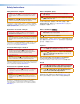
Safety Instructions Safety Instructions • English WARNING: This symbol, , when used on the product, is intended to alert the user of the presence of uninsulated dangerous voltage within the product’s enclosure that may present a risk of electric shock.
Conventions Used in this Guide In this user guide, the following are used: ATTENTION: An attention is used to indicate potential damage to product or property. CAUTION: A caution indicates a potential hazard to equipment or data. NOTE: A note draws attention to important information. Specifications Availability Product specifications are available on the Extron website, www.extron.com. Copyright © 2013 Extron Electronics. All rights reserved.
Contents Introduction............................................................ 1 Features.............................................................. 1 Application Example............................................ 2 Installation............................................................... 3 Installation Considerations................................... 3 Installing the Speaker..........................................
Introduction This user guide contains information about the Extron FF 220T Flat Field speaker. This speaker is designed for use in plenum rated ceiling spaces and can be dropped into a square (2-foot by 2-foot or 600 mm by 600 mm) or rectangular (2-foot by 4-foot or 600 mm by 1200 mm with supplied cross bars) false ceiling tile space on a T-bar grid. The FF 220T features a low profile design that houses a 3-inch driver and has the appearance of a standard ventilation grill.
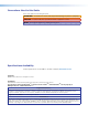
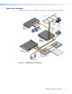
Application Example The illustration below is one example of configuring a system using the FF 220T speakers. Desk Microphones VCR DVD DOC CAM TOP LAP PC ON OFF LAY DISP E MUT EEN SCR UP UT Extron TLP 700TV 7" TouchLink™ Tabletop Touchpanel 2 TP -23 RS OU A B L R L 6 O DI 3 5 T PU 4 8 IN R 7 AU 2 1 UT L B RG, R-Y B-Y R TP OU D LISTE 1T23 U S I.T.E.
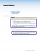
Installation The Installation section describes: • Installation Considerations • Installing the Speaker Installation Considerations ATTENTION: Installation and service must be performed by authorized personnel only.
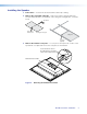
Installing the Speaker 1. Power down — Power down all attached devices before proceeding. 2. Remove the suspended ceiling tile — Remove the square ceiling tile where the FF 220T will be installed as shown below. If the ceiling has rectangular tiles, cut the tile in half. Cut Material Draw Line At Halfway Point Rectangular Ceiling Tile Ceiling Tile T-rail Crosspiece (supplied) 3.
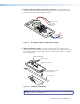
4. Routing cables through the transformer cover plate — Slide and remove the terminal cover plate. The transformer cover plate is mounted to the speaker with the transformer side down. See the illustration below. (Black) To Speaker (-) Terminal C O M C N O C M 16 16 W W 8 8 W W 4 4 W W 2 2 W W 1 1 W W N C (Red) To Speaker (+) Terminal 0V 70 V 10 To Second Speaker Black (-) Red (+) Black (-) Red (+) From Amplifier (70V/100V) Figure 3.
When using speaker wires without a conduit — Secure the cable clamp adapter (included) to the cover plate and insert the wires through the clamp. Tighten the clamp screws. See the following illustration. Cable Clamp Adapter Transformer Cover Plate Secondary Support Cable Pass Through Loop Rear of Speaker Figure 5. Wiring Without Conduit 6.
b. Route the two wires from the amplifier through the cover plate hole to the transformer side. c. Strip 3/16 inch (5 mm) from the wire ends and keep the wire end strands together by twisting them. Do not tin the wires. d. Secure the wires to the appropriate taps on the captive screw connectors of the seven-connector terminal block (on the transformer side of the cover plate) as indicated on the tap label. See the note below.
8. Connect wires from the transformer to the speaker. a. Keep the wire strands together by twisting them (do not tin the wires). b. Connect the red positive (+) wire to the + speaker terminal and connect the black negative (-) wire to the - speaker terminal as shown below. Transformer Cover Plate Red Wire To transformer Black Wire Figure 9. Rear of Speaker Wiring the Speaker to the Transformer c. Proceed to step 10.
b. Connect the red positive (+) wire to the + speaker terminal and the black negative (-) wire to the - speaker terminal depending on whether one or two speakers are being connected. Red Wire From Amplifier To Second Speaker From Amplifier To Second Speaker Black Wire Red Wire From Amplifier Black Wire Two Speakers One Speaker Figure 11. Wiring the Speaker Terminals Finishing Steps, All Installation Types 10.
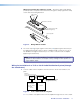
For installations in a rectangular ceiling grid, replace half of the rectangular tile which was cut in half in step 2. Install the supplied T-rail crosspiece, then place the speaker on the grid and position it so that the speaker edges are hidden by the support rails and T-rails, as shown below. Extron FF 220T Ceiling Speakers Ceiling Tile Existing Ceiling Tile Rails T-rail Crosspiece (supplied) Figure 13.
13. If secondary support cables are being used, install them. See the illustration below. NOTE: Observe all applicable building codes and local ordinances when installing the speaker. Anchor this end to a suitable secure point. Route the secondary support cable through the line retainer and bend-up tab. Secondary Support Cable Bend-up Tab Figure 14. Installing a Secondary Support Cable a. Temporarily remove a ceiling tile adjacent to the speaker and set it aside. b.
Reference Information Dimensions A A D C B U.S. Version Metric Version A 23.75" (60.35 cm) 57.4 cm (23.4") B 3.25" (8.3 cm) 8.3 cm (3.25”) C 8.0" (20.32 cm) 20.32 cm (8.0”) D 3.5" (8.89 cm) 8.89 cm (3.
Extron Warranty Extron Electronics warrants this product against defects in materials and workmanship for a period of five years from the date of purchase.