
Setup Guide User Manual

Setup Guide — Extender Series
(Continued on reverse side)
W
Installation and service must be performed by
authorized personnel only. These products
must be used with UL approved, grounded
electrical boxes.
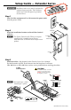
Step 1
Turn all of the equipment off and disconnect the power cords
from the power source.
Step 2
Select the installation location and install the electrical
wall box.
N
The Extron Extender AAP EX does not require
a wall box if it is installed into an Extron
HSA 400 Series or HSA 800 Series surface access
product.
Step 3
Attach the cables. See chapter 2 in the Extender Series User’s Manual.
For the Extender AAP EX, install the unit into the faceplate of an Extron
HSA 400 Series or HSA 800 Series surface access product before attaching the cables.
To RGB
Video Equipment
Extender Series
9
-1
8
VD
C
wer
Gain
(S
w
itch
is on
th
e
lo
w
er circu
it b
oa
rd
.)
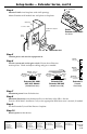
Maximum
Max. peaking
& gain
Medium
– Mid-lev
el
peaking & gain
Normal
Unity
gain
www.extron.com
33-612-02
Rev. C
02 05
L
Audio
R
Sleeve (s)
Left Tip
Left Ring
9-18 VDC
Power
Sleeve (s)
Left Tip
Right Tip
Left Ring
Right Ring
9-18 VDC
Power
Audio
Unbalanced Output
Left Tip
NO Ground Here
Sleeve(s)
Right Tip
NO Ground Here
Balanced Output
Sleeve(s)
Left Tip
Right Tip
Left Ring
Right Ring
L
Audio
R
L
Audio
R
Do not tin the wires!
CAUTION
For unbalanced audio, connect the
sleeve(s) to the ground contact.
DO NOT connect the sleeve(s) to
the negative (-) contacts.
Installation
Cable
Cable Clamp
Wall Stud
Screws or
Nails
N
Horizontal sync = black.
Vertical sync = yellow.