
User Guide User guide

EDID101H • Installation 11
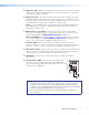
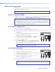
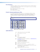
Record EDID to a Memory Slot:
To record EDID from a connected display:
1. Set DIP switches A and B (
g
) to the down (off) position.
2. Turn the rotary switch (
f
) to the desired user slot location (1through F) to store the
display EDID.
3. Connect the display device to the Output connector of the
EDID101H (see figure 3,
c
on page 5).
4. Connect a power source and apply power to the EDID 101H.
The green power LED lights when power is available.
5. Power on the display device.
6. Press EDID STORE (
e
) once to store the display EDID to the
memory slot selected in step 2. The LED (
d
) flashes amber.
When the LED returns to green, the EDID is stored.
NOTE: An EDID stored in user slots 1 through F is saved until a new EDID is
manually stored to that slot or the device is reset.
Assign Pre-programmed EDID:
Configure the DIP switches and rotary switch corresponding to the desired native rate, video
format, and audio format (see EDID101H Memory Slot Locations on page9).
NOTE: Configuring the EDID 101 rotary and DIP switches allow a user to select a
pre-programmed EDID file based on the native rate of a display (such as 1280x1024
@ 60 Hz), but does not force a video source to output that rate. Since EDID reporting
is not limited to a single video rate (the native rate), each Extron EDID also lists other
common video rates for use by the video source.
EDID101H Configuration
The EDID 101H can be configured prior to installation. EDIDs are recorded from a display or
a pre-programmed EDID is selected.
TIP: If access to the EDID101H is restricted after mounting or installation, configure
the EDID101H prior to the installation.
POWER
12V
0.3A MAX
EDID
STORE
AB
AB
C
OUTPUTINPUT
EDID
HPD
0
1
2
3
4
5
6
7
8
9
A
B
C
D
E
F
ON
123
1
2 3
4 5 6
9
7
8
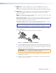
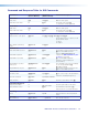
Record EDID Automatically:
1. Set DIP switches A and B (
g
) to the down (off) position.
2. Turn the rotary switch (
f
) to position 0.
3. Connect a power source and apply power to the EDID101H.
The green power LED lights.
4. Connect the display device to the Output connector of the
EDID101H (see figure 3,
c
on page 4).
5. Power on the display device.
6. The display EDID data is automatically read and stored to rotary switch position 0.
NOTE: The EDID stored in this memory slot updates automatically when a different
display is connected to the output. It reverts to the default EDID after a power
cycle.
POWER
12V
- - A MAX
EDID
STORE
AB
AB
C
OUTPUTINPUT
EDID
HPD
0
1
2
3
4
5
6
7
8
9
A
B
C
D
E
F
ON
123
1
2 3 4 5 6
8
9
7