User Guide SCALERS AND SCAN CONVERTERS DVS 304 Series Video and RGB Scalers 68-1039-01 Rev.
Precautions Safety Instructions • English Warning This symbol is intended to alert the user of important operating and maintenance (servicing) instructions in the literature provided with the equipment. Power sources • This equipment should be operated only from the power source indicated on the product. This equipment is intended to be used with a main power system with a grounded (neutral) conductor. The third (grounding) pin is a safety feature, do not attempt to bypass or disable it.
FCC Class A Notice This equipment has been tested and found to comply with the limits for a Class A digital device, pursuant to part 15 of the FCC Rules. Operation is subject to the following two conditions: 1. This device may not cause harmful interference. 2. This device must accept any interference received, including interference that may cause undesired operation.
Contents Introduction............................................. 1 SIS Communication and Control............ 30 DVS 304 Series Description............................ 1 DVS 304 Models.......................................... 1 DVS 304 DVI Models................................... 2 Features.......................................................... 2 Controlling the DVS 304 Devices................... 3 Options and Accessories................................ 4 Host to Scaler Communications..............
Menu System........................................... 75 Default Cycle Menu.................................. 75 Main Menu............................................... 75 Start Auto Image Menu........................... 76 Input Configuration Menu...................... 76 Picture Control......................................... 76 Output Configuration Menu................... 77 Audio Configuration Menu..................... 77 Memory Preset Menu............................... 77 IP Configuration Menu.....
Introduction This manual contains information about the Extron® DVS 304 Series of scalers with instructions for experienced installers on how to install, configure, and operate the equipment. In this manual the terms “DVS,” “digital video scaler,” and “scaler” are used interchangeably and refer to any DVS 304 Series model.
DVS 304 DVI Models The DVS 304 DVI offers simultaneous digital and analog scaled outputs through the DVI-I port. Simultaneous analog scaled output is also available on BNC connectors. A total of 70 output scan rates are available from VGA (640x480) to WUXGA (1920x1200) resolution, as well as HDTV at 720p, 1080i, and 1080p/60 Hz.
Buffered video outputs — • DVS 304 models – Five rear-panel BNC connectors and one VGA-type 15-pin HD connector provide connections for RGB or Y, R-Y, B-Y output. Both outputs are active at all times for simultaneous output. • DVS 304 DVI models – Five rear-panel BNC connectors and one DVI-I connector provide analog and digital output (DVI-I) and analog output (BNC). All outputs are active at all times for simultaneous output of RGB or Y, R-Y, B-Y. DVI-D output is disabled for RGB pass-though.
Options and Accessories The DVS 304 series optional equipment includes: • IR 902 remote control — The Extron IR 902 (part #70-495-01) is an infrared remote control that replicates most of the front panel controls of the digital video scaler (except the Menu and Next buttons). • SDI input card — Serial digital interface (SDI) input can be added to a DVS 304 model by the installation of an SDI input card (part #70-168-01).
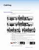
Cabling This section describes how to connect cables to a DVS 304 series device. Rear Panel Cabling The illustration below shows the all possible rear panel features of the audio and non-audio models. 5 (Optional) 8 DVS 304 AD 100-240V .
d Video input 1: Composite video — Connect a composite video signal to this female, BNC connector. 1 e Optional SDI (serial digital interface) input connector — Connect an SDI signal to this female BNC connector. During setup, the SDI input can be assigned to one of the other unused inputs. f Video input 2: Composite/S-video/Component — Connect composite video, S-video, and component video signals. Connect cables for the appropriate signal type, as shown here.
i RGB (RGBHV, RGBS, RGsB) or HD component (R-Y, Y, B-Y) video BNC outputs — Connect cables from a display device to these BNCs for a scaled or pass-through RGB or a scaled component video output. The output can be scaled to 69 different output rates (see table on page 15). NOTES: RGB pass-through is available on analog outputs only. The DVI output is disabled for RGB pass-through.
l Remote (RS-232/contact closure) port — This 9-pin connector provides for twoway RS-232 communication. See the “SIS Communication and Control” chapter for information on how to install and use the control software and SIS commands. The default protocol is 9600 baud, 1 stop bit, no parity, and no flow control.
Operation This section of the manual discusses the operation of a DVS 304 device, and is divided into four sections: • Front Panel Overview • Menus, Configuration, and Adjustments • Front Panel Lockout • Setting up the DVS to Work with a Matrix Switcher Front Panel Overview DVS 304 1 2 3 4 MENU VIDEO AND RGB SCALER ADJUST NEXT IR 1 2 3 4 5 6 7 Figure 8. Typical DVS 304 Device Front Panel Features a Input LEDs — The LED of the selected input lights when pressed.
Menus, Configuration, and Adjustments Scaler configuration and adjustments can be performed by using the embedded Web pages and the Windows-based control program (see the “SIS Communication and Control” chapter for details) or by using the front panel controls and the menus displayed on the DVS unit’s LCD screen. These menus are used primarily when the scaler is first set up.
Displays specific model name (for example DVS 304 DVI AD) Power on EXTRON ELECTRONICS 2 sec. DVS 304 xxx xx Default Cycle Displays specific model part number (for example 60-1027-04) 2 sec. 60-xxxx-0x FW version 1.00 2 sec. 2 sec. INPUT 1 COMPOSITE 2 sec.
Start Auto Image Auto image an input to “auto size” and “auto center” the image to fill the screen. The processor measures the sync frequencies from incoming video sources and uses an internal table to set the active image area, total image area, and the sampling frequency. If an unknown input is connected to the unit, the processor measures and estimates the resolution of the incoming video. The DVS 304 can be set to automatically auto-image newly detected inputs (see page 21). Default Cycle 2 sec.
Input 1 video type Input 1 can only input composite video, other video types are not selectable. Input 2 video type Rotate either the Adjust horizontal ([) or Adjust vertical ({) knob while in the Input 2 submenu to select the appropriate video format (composite, S-video, YUVi, YUVp/HDTV, YUV Auto) for input 2. When input 2 is set to YUV Auto, the scaler detects if YUVi or YUVp/HDTV is applied and sets the input accordingly. The default is YUVi video.
Picture Control The Picture Control menu includes all of the picture settings for the scaler including positioning, sizing (horizontal and vertical control), brightness and contrast, color saturation, tint, detail (sharpness of the picture), and zoom (see figure 14). The pan feature is only available when zoom is over 100%. Color, tint and pan controls are available for applicable signals only. INPUT CONFIG Tint adjustment is applicable only for NTSC composite or S-Video inputs.
Resolutions and Refresh Rates Rotate the Adjust horizontal ([) knob while in this submenu to select one of the available combinations of output resolutions and refresh (vertical scanning) rates. Rotate the Adjust vertical ({) knob while in this submenu to select one of the available refresh rates. The default resolution and rate for the DVS 304 series is 1024x768 @ 60Hz.
Audio Configuration (Audio Models Only) Audio Configuration allows the input level to be adjusted between –15 dB to +9 dB for each audio input. OUTPUT CONFIG MENU AUDIO CONFIG IN1 LEVEL 0dB NEXT NEXT (audio models only) Input level Adjust the input gain/attenuation from -15dB to +9dB of the selected input. Figure 16. Audio Configuration Menu Overall volume control is available through SIS commands or IR remote control.
Save Memory Preset From this submenu, the picture control information for the currently selected input can be saved to memory. Up to three memory presets can be saved per input. 1. Using either the Adjust horizontal ([) or Adjust vertical ({) knob, select either N/A, 1, 2, or 3 to select a preset. The default is . 2. To save the preset, press the Next button. NOTE: The presets are saved in nonvolatile memory, so powering down the DVS 304 will not lose the presets.
IP Configuration The IP Configuration menu displays the IP address of the unit, the Subnet mask, and Gateway IP address. MEMORY PRESETS MENU IP CONFIG I 196.168 P 254.254 NEXT S 255.255 M 000.000 NEXT View IP address of the unit. G 000.000 M 000.000 NEXT NEXT View gateway IP address of the unit. View the subnet mask of the unit. Figure 19. IP Configuration Menu To change an IP address, do the following: 1. Press and hold the Input 4 and Next buttons simultaneously for 2 seconds.
Auto-Image™ When enabled and a new input frequency is detected, the DVS first applies an existing Auto Memory for the signal (if Auto Memory is enabled), or if no entry exists, performs an automatic Auto-Image on the new signal. With Auto Image disabled, the DVS 304 will apply default values to a new input if no Auto Memory exists (if Auto Memory is enabled). Default is Off. See the table on page 21 for a full description of the interaction between the Auto-Image and Auto Memory settings.
OSD label Use the On-Screen Display (OSD) label menu to determine the time allotment for an input label or a user defined OSD label. Input labels are generic labels shown for inputs 1, 2 and 3. For input 4, the user can create a custom OSD label to display. The OSD labels are displayed (white box, black text) in the top left corner. The OSD label can be turned off by setting its duration to Off from the Advanced Configuration menu. For OSD text, note the following: • Line 1 displays the input number.
Auto Memory The DVS 304 stores 16 auto memories with input and picture control data for each input. The default settings enables these memories to automatically recall input and picture controls for signals that have been previously applied. By disabling auto memories, the DVS 304 will treat every newly applied input as a new source. Default is on.
Picture-in-picture mode The DVS 304 can display two image sources on the screen simultaneously. Keep in mind that when using the PIP feature, one image source must be low-resolution (composite, S-video, YUVi and RGBcvS) video, while the other must be high resolution (YUVp/HDTV, RGB scaled, SDI) video. If these conditions are not met (for example, two low resolution video inputs or two high resolution inputs are selected), the PIP mode will exit. To go into picture-in-picture mode, do the following: 1.
Using the swap feature Use the swap feature to switch the active main window input with the current PIP input. For example if the main window is Input 4 (RGB scaled) and the PIP window is Input 1 (composite), applying the swap command results in Input 1 becoming the main window and Input 4 the PIP window. For audio models (DVS 304 A, DVS 304 AD, DVS 304 DVI A, and DVS 304 DVI AD), you can set audio to follow the main (default) or PIP window.
Resetting the Unit There are four unit reset modes (numbered 1, 3, 4, and 5), These are available by pressing the recessed Reset button on the rear panel with a pointed stylus, pen, or similar to access it. See the following table for a summary of the reset modes. CAUTION: Review the reset modes carefully. Using the wrong reset mode may result in unintended loss of flash memory programming, port reassignment, or processor reboot.
System Reset For a scaler reset, the DVS 304 can return to default values by holding down the Input 1 button while simultaneously plugging in the power cord. The System Reset message will be displayed on the LCD screen. Front Panel Lockout (Executive Modes) To prevent accidental changes to settings, press the Menu and Next buttons simultaneously for 2 seconds to enable the DVS 304’s front panel lockout mode, also known as executive mode 1.
Setting up the DVS to Work with a Matrix Switcher The Sync to Matrix tool is a powerful tool that can simplify the control system necessary when using an Extron matrix switcher and a DVS 304. The Sync to Matrix script can sense when a new tie is made on the matrix is routed to the DVS and automatically recalls the input preset associated with the input on the matrix switcher. The input preset recalls all the settings for the input including the signal format, input sampling settings, and picture controls.
3. On the DVS 304, configure the input as follows: a. Switch to input 4 on the DVS. b. Set the following input sampling settings as desired: signal type, horizontal and vertical start, pixel phase, total pixels, active pixels, and active lines. NOTE: Do not use auto detect setting for the input type when using input presets. It is also recommended to disable auto image and auto memory when using input presets. c.
f. Click the Take button to tie the DVS 304’s input to the selected switcher output. The program creates a custom script that is then be loaded onto the DVS 304. The Status box updates with the status of the script on the DVS 304, showing if the DVS 304’s script is connected to the matrix switcher, and showing the current tie associated with the selected output.
Minimizing Synchronization Problems Without Using the Sync to Matrix Feature This section describes how to manually implement the equivalent of the Sync to Matrix feature without using a script loaded on the DVS 304, and instead relying on a control system.
SIS Communication and Control The DVS 304 can configured and controlled via a host computer or other device (such as a control system) attached to the rear panel RS-232 connector or the LAN port. Control is made using the Extron Simple Instruction Set (SIS™) of commands, or by using the Signal Processing Products Control Program (SPPCP), or the devices internal HTML Web pages. This section describes SIS communication and control.
Copyright Information ] © Copyright 2010, Extron Electronics, DVS 304 series, Vx.xx Thur, 17 June 2008 11:27:33 ] The copyright message is displayed upon connecting to IP Link product via TCP/IP or Telnet. Vx.xx is the firmware version number. The current date and time are displayed. This is followed by a Password prompt if a password has been set. Password Information The ] Password: prompt requires a password (administrator level or user level) followed by a carriage return.
Command and Responses Using the Command and Response Tables The following are either Telnet (port 23) or Web browser (port 80) commands. There are some minor differences when you are implementing these commands via Telnet or via URL encoding using a Web browser. All commands listed below will work using either connection method but, due to some limitations of the Web browser, the encapsulation characters are modified to make sure that the Web browser will properly handle them.
Symbol Definitions • = Space ] = Carriage return with line feed } = Carriage return with no line feed E = Escape 14, 24, 27, 28 = Superscripts indicate the error message displayed if the command is entered incorrectly or with invalid parameters. See “Error Response References” section. X! = Specific port number (01-99) X@ = Command data section NOTE: For Web encoding only: data is directed to the specified port and must be encoded if it is non-alphanumeric.
X3# = Password (12 characters = maximum length; no special characters are allowed.) NOTE: A user password cannot be assigned if no administrator password exists; the E14 error code is returned. If the administrator password is cleared, the user password is also removed.
X7@ = Input selection: 2 or 4 X7# = Input video format: 1 = composite, 2 = S-video, 3 = RGBcvS, 4 = YUVi, 5 = YUVp/HDTV, 6 = RGB scaled, 7 = RGB pass through, 8 = auto detect/YUV auto, 9 = SDI NOTE: RGB pass-through is only on analog output for DVI models. The DVI output is disabled for RGB pass-through. X7$ = H start: 0 to 127 for video inputs; 0 to 255 for RGB and YUVp/HDTV inputs. X7% = V start: 0 to 93 for video inputs; 0 to 255 for RGB and YUVp/HDTV inputs.
X10) = PIP window input selection: 0 to 4 X10! = Audio level adjustment range: -15 to +9 dB X10@ = Audio gain adjustment range: 0 to 9 dB X10# = Audio attenuation adjustment range: -15 to 0 dB X10$ = Volume range: 000 to 100, (always returns 3 digits) X10% = PIP window size: 1 = 1/4, 2 =1/9, 3 = 1/16, 4 = 1/25, 5 = Side by side normal, 6 = Side by side full screen X10^ = PIP audio setup: 1 = follow main window, 2 = follow PIP window, 3 = toggle audio X10& = RGB delay: 0 to 10 (0 to 5 seconds in 0.
SIS Command and Response Table Command ASCII Command (host to scaler) Response (scaler to host) Additional Description Input selection Video and audio X7!! In X7!• All] Select video and audio from input X7!. Video X7!& In X7!• RGB] Select video from input source X7!. Audio X7!$ In X7!• Aud] Select audio from input source X7!. Input video type (input 2 and input 4) Set video type X7@* X7# \ X7@ Typ X7# ] Set input X7@ to format X7#.
Command ASCII Command (host to scaler) Response (scaler to host) Additional Description Active pixels Specify a value 12*X7*# Apx X7* ] Adjust the active pixels to specified value. Increment value +12# Apx X7* ] Increase the active pixels. Decrement value - 12# Apx X7* ] Decrease the active pixels. View 12# X7* ] Show the active pixels. Specify a value 13*X7(# Aln X7( ] Adjust the active lines to specified value. Increment value +13# Aln X7( ] Increase the active lines.
Command ASCII Command (host to scaler) Response (scaler to host) Additional Description Color (available for PAL and NTSC only) Set a specific value X8% C Col X8% ] Set color level to X8%. Increment up +C Col X8% ] Increment color level. Increment down –C Col X8% ] Decrement color level. View C X8% ] View current setting. Tint (available for NTSC composite and S-video only) Set a specific value X8% T Tin X8% ] Set tint level to X8%. Increment up +T Tin X8% ] Increment tint level.
Command ASCII Command (host to scaler) Response (scaler to host) Additional Description Horizontal size Specific value X8& : Hsz X8& ] Set horizontal sizing to X8&. Increase size +: Hsz X8& ] Widen the window. Decrease size –: Hsz X8& ] Make the window narrower. View : X8& ] View horizontal sizing value X8&. Specific value X8& ; Vsz X8& ] Set vertical sizing to X8&. Increase size +; Vsz X8& ] Make the window taller. Decrease size –; Vsz X8& ] Make the window shorter.
Command ASCII Command (host to scaler) Response (scaler to host) Additional Description Memory presets (inputs 1 to 4) Recall preset 1* X9% . 1RprX9%] Recall memory preset X9% for selected input. Save preset 1* X9% , 1SprX9%] Save memory preset X9% for selected input. Input presets (input 4 only) Recall preset 2* X9^ . 2RprX9^] Recall input 4 preset X9^ . Save preset 2* X9^ , 2SprX9^] Save input 4 parameters to X9^ .
Command ASCII Command (host to scaler) Response (scaler to host) Additional Description Volume control (audio models only) Set specific volume X10$V Vol X10$ ] Set volume to X10$. Increment +V Vol X10$ ] Increase volume. Decrement -V Vol X10$ ] Decrease volume. View V X10$ ] View current volume setting. Crop 1J Tst 1] Set crop test pattern on. Alternating pixels 2J Tst 2] Set alternate pixels on. Color bars 3J Tst 3] Set color bars on. Off 0J Tst 0 ] Set test pattern off.
Command ASCII Command (host to scaler) Response (scaler to host) Additional Description On Screen Display (OSD) duration Select speed 20*X9*# Dur X9* ] Set the OSD duration View speed 20# X9* View the on screen display time. ] Text label (OSD) (Input 4 only) Write name E X8$NI] Nam 4X8$} Write text X8$ for input 4. Read name ENI] X8$} View text label for input 4 PIP size 16*X10%# Pmd X10%] Select size of PIP window. View 16# X10%] View PIP window size.
Command ASCII Command Response (host to scaler) (scaler to host) Additional Description Front panel security lockout (Executive Mode) Enable 1X Exe1] Allow limited front panel adjustments only. Disable 0x Exe0] Allow adjustments/selections to be made from front panel. View status X X%] Show mode status.
DVS 304 Series • SIS Communication and Control 45 W 0TC W 1%2AX6(TC W 1TC E0TC } E1 * X6( TC } E1TC } View current connection port timeout Set global IP port timeout View global IP port timeout X6( ] Pti1 * X6( X6( ] Pti 0 * X6( ] ] (processor to host) Response Additional description 3Q 3Q 2Q 2Q 1Q 0Q 1.00(1.37-DVS 304 Series -Fri, 12 Aug 2005 03:28:10 GMT) X1!(plus web ver.desc-date/time)] 0.06 X1! ] 1.
DVS 304 Series • SIS Communication and Control 46 1I 2I 3I 4I Request model name Request model description Request system memory usage Request user memory usage Ego ] Est ] Enm## ] W1AE| W0AE| WAE| E1AE} E0AE} EAE} 27 Start events24 24 27 {string} ] ## = number of events running. Stop all programmed events. Initiate all programmed events. Write data string X3( from event X3%, buffer X3^, offset by X3&. Read string from event X3%, buffer X3^, offset by X3&, X4$ bytes.
DVS 304 Series • SIS Communication and Control 47 W X4% CR| WX4% SM| WX4% %2C X7)%2C X4&SM| W X1$ %2C X1% CM| WX1$ %2C X1%CM| E X4% CR} E X4% SM} E X4%, X4^, X4&, SM} E X1$, X1% CM } E CM } Read e-mail events Send e-mail (event) Send e-mail (using a different file) 24 Set mail server IP address, unit domain name24 Read mail server IP address, unit domain name24 28 E X1@ CN } E UB } WX1@ CN| Ipn • X1@] Response from command ] X1$, X1%] Ipm • X1$, X1%] Eml X4% ] Eml X4% ] X4^, X4& ] lpr5,jd
DVS 304 Series • SIS Communication and Control 48 W%20CN| WCN| W X1# CT| WCT| E • CN } E CN } E X1#CT } E CT } E X#CZ} Set unit name to factory default24 Read unit name Set time/date24 Read time/date Set GMT offset24 IpxX3$ ] X3$ ] Idh1 ] Idh0 ] IdhX% ] WX3$CX| WCX| W1DH| W0DH| WDH| E X3$CX} ECX } E1DH } E0DH } EDH } Set daylight saving time24 Read daylight saving time Set DHCP on24 Set DHCP off 24 View DHCP mode X% = 0 (off) or 1 (on).
DVS 304 Series • SIS Communication and Control 49 X1*] Ips•X1( ] X1( ] Ipg•X1$ ] X1$ ] WCH| WX1(CS| WCS| W X1$CG| WCG| W X6$%2C X1$EB| ECH } E X1(CS} ECS} E E X1$CG} ECG} E X6$,X1$EB} Read hardware address (MAC) Set subnet mask24 Read subnet mask Read gateway IP address Set broadcast mode Clear/remove all passwords (administrator and user) Set the administrator access password. (X3# is 4-12 alphanumeric characters) The password is case sensitive.
DVS 304 Series • SIS Communication and Control 50 Ipu•X3# ] WX3#CU| E X3#CU} X3#] VrbX2@] WCU| W X2@CV| ECU} E X2@CV} X5@] WCK| ECK} Read connection’s security level Pmt{port #}] Pmt00023] Pmt00000] {port #}] Pmh{port #}] Pmh00080] Pmh00000] {port #}] W23MT | W0MT | WMT | W{port #}MH | W80MH | W0MH | WMH | E23MT} E0MT} EMT} E{port #}MH} E80MH} E0MH} EMH} Disable Telnet port map 24 Read Telnet port map Set Web port map 24 24 Set Web port to default value of 80 Set Telnet to the default po
DVS 304 Series • SIS Communication and Control 51 {port #}] WMD | E0MD} EMD} Read Direct Access port map 24 Additional description Remote client IP address: port number, time/date when connection was made, total connection time ] Remote client IP address: port number, time/date when connection was made, total connection time ] Remote client IP address: port number, time/date when connection was made, total connection time ] ...
DVS 304 Series • SIS Communication and Control 52 (See below.) (processor to host) Response http://192.168.254.254/mypage.html?cmd=WSF| W%2FCJ| W%2E%2ECJ| WCJ| E / CJ} E ..CJ} E CJ} Move up one directory View current directory A directory does not actually exist until a file has been copied into the path.
DVS 304 Series • SIS Communication and Control 53 W%2FEF| W%2F%2FEF| E/EF} E//EF} Erase current directory and its files24, 28 Erase current directory and subdirectories24, 28 Zpa ] ZapI ] WZI| EZI} Image setting reset EZQQQ} Absolute system reset WZA| Zpq ] WZQQQ| EzXXX} EZA} Zpx ] WzXXX| Set audio (DVS 304 A and DVS 304 A D only Zpf ] WZFFF| EZFFF} Reset all device settings to factory default24 Ddl] Ddl] Del • {filename}] (processor to host) Response Erase flash memory24 comma
Signal Processing Products Control Program The Extron Signal Processing Products Control Program (SPPCP) offers another way to control the DVS 304 via RS-232 or Ethernet connection in addition to the SIS commands. This section describes SPPCP installation, communication, and control.
3. Follow the instructions that appear on the screen. By default, the installation creates a C:\Program Files\Extron\Signal Processing directory and places a shortcut icon in it. Installation from the Web Site 1. On the Extron Web site (www.extron.com), select the Download tab. 2. On the Download Center screen, select Software from the side-bar menu on the left. 3. Locate the Signal Processing Products Control Program file from the list and click on it. 4.
Using the SPPCP The Signal Processing Products Control Program (SPPCP) is used to configure and operate the DVS from the PC on which the program resides. Orientation The SPPCP main window has three tabs: Control, I/O Configuration, and Advanced Settings. Figure 30. The Control Program Main Window The menu bar on the main window shows File, Options, Tools, and Help. Click on each as desired.
SPPCP Menus File menu Click on this to open a drop-down menu displaying six selectable options: Connect, Disconnect, Save Configuration..., Restore Configuration..., File Manager, and Exit. • Connect — Select this to reconnect the DVS (or connect a new device) when it has been disconnected from the Signal Processing Products Control Program. Follow the steps in the section “Starting the SPPCP”. • Disconnect — Select this to disconnect the unit from the Signal Processing Products Control Program.
Tools menu Click on this to open a drop-down box displaying nine selectable options: Data View/Trace Window... Sync Scaler to Matrix Switcher..., System Settings..., Reset (has a secondary drop down box), and Update Firmware.... • Data View/Trace Window... — Select this to open a separate window in which the transmit and receive (Tx/Rx) data between the control software on the host PC and the DVS can be viewed in ASCII format (see figure at right).
If the sync to matrix script needs to be removed or updated, click Remove Sync Scripts. • System Settings... — Select this to open a secondary window. This allows changes to be made to various device settings: IP and RS-232 connections, date/time, and passwords. Select the applicable tab, change the settings as desired, and click Submit to make the changes effective. NOTE: Changing the IP settings may result in loss of connection to the LAN Figure 32.
To download and install the Firmware Loader application: 1. Go to www.extron.com. 2. Enter “Firmware Loader” in the Search field and press Enter. 3. Locate the Firmware Loader application in the search results and click Download Now! 4. Follow the on-screen prompts to complete the download. To update the device’s firmware: 1. From the SPPCP Tools menu, select Update Firmware. The SPPCP minimizes and the Firmware Loader application opens.
Figure 35. Process Running 5. When the file upload is complete (after file verification and the device restarting), click on the X at top right, or on File > Exit to exit the Firmware Loader. The SPPCP window restores itself. 6. Connection the DVS 304 must be reestablished since the connection is lost during firmware upload. Open the SPPCP Connect dialog box and re-enter the connection information to re-establish communication with the DVS 304.
Control Tab The Control tab displays the current configuration of the DVS 304. An output view window is visible, and an I/O Control section, with signal type indicators and numbered boxes representing the audio/video and PIP inputs. Also shown on the Control tab are the PIP control buttons, current picture adjustment values, input 4 and user presets, as well as Mute, Freeze and Auto Image buttons. A volume control slider is also available. Figure 37.
• Input 4 Presets/OSD — The specific settings for size, centering, contrast, brightness, detail, zoom, and input configuration for input 4 can be saved to a preset. Up to 128 input presets can be saved. A saved preset can be recalled as desired. Select a preset number and click Save or Recall as applicable. NOTE: Saving to an existing preset overwrites the prior saved data with the new. In addition this section enables the OSD text to be set for input 4.
• Output Config — To configure an output’s resolution, refresh rate, sync format, or sync polarity, select the desired values from the respective drop-down list. • PIP Audio Follow — PIP Audio Follow option of the I/O Configuration tab assigns audio to either the main image or the PIP image. Advanced Settings Tab The Advanced Settings tab allows advanced functions to be configured. These include test pattern selection, RGB delay setting, and advanced functions, used during initial setup. Figure 39.
Ethernet Control The DVS 304 features an on-board Web server, displayed as a set of default Web pages. These pages allow you to control and operate the DVS 304 unit through its Ethernet port, connected via a LAN or WAN, using a Web browser such as Microsoft’s Internet Explorer® (version 5.5 or higher). This section describes these default Web pages, which are always available and cannot be erased or overwritten.
7. Click OK. The scaler checks several possibilities, in the following order, and then responds accordingly: • Does the address include a specific file name, such as 10.13.156.10/file_ name.html? If so, the DVS 304 downloads that HTML page. • Is there a file in the scaler’s memory that is named “index.html”? If so, the scaler downloads “index.html” as the default start-up page. • If neither of the above conditions is true, the scaler downloads the factory-installed default start-up page, “nortxe_index.
Configuration The Configuration tab includes pages that show the current system settings, scaler settings, passwords and firmware upgrade data for the DVS 304 Series. System Settings page The Systems Settings page consists of fields where you can view and edit IP administration and system settings. Date and time information can be easily updated. Figure 41. System Settings Page IP settings fields The IP settings fields provide a location for viewing and editing settings unique to the Ethernet interface.
IP Address The DVS 304 IP Address field contains the IP address of the connected scaler. This value is encoded in the flash memory in the scaler. Valid IP addresses consist of four 1-, 2-, or 3-digit numeric subfields separated by dots (periods). Each field can be numbered from 000 through 255. Leading zeroes, up to 3 digits total per field, are optional. Values of 256 and above are invalid. The default address is 192.168.254.
4. If appropriate, select the Daylight Saving radio button for the DVS’s region, to turn on the daylight saving time feature. NOTE: When a locations daylight savings time is turned on, the switcher automatically updates its internal clock between Standard Time and Daylight Savings Time in the spring and fall on the date that the time change occurs in the country or region selected. When Daylight Savings Time is turned off, the switcher does not adjust its time reference.. 5.
Passwords Page The fields on the Passwords page are for entering and verifying administrator and user passwords. Passwords are case sensitive and are limited to 12 upper case and lower case alphanumeric characters. Each password must be entered twice: once in the Password field and then again in the Re-enter Password field. Characters in these fields are masked by asterisks (*****). If you do not want to password protect an access level, leave the Password field and the Re-Enter password field blank.
Firmware Upgrade page The Firmware Upgrade page provides a way to replace the firmware that is coded on the scaler’s control board without taking the scaler out of service. Figure 44. Firmware Upgrade Page NOTE: The Firmware Upgrade page is only for replacing the firmware that controls all scaler operation. To insert your own HTML pages, see “File Management” later in this chapter. Ensure that your PC is connected to the DVS 304 scaler via the scaler’s Ethernet port.
File Management The File Management page (located under the File Management tab), is a useful tool that allows you to use and upload existing and custom Web pages. Custom pages can be developed using a third-party Web page development program such as Microsoft Office FrontPage or Adobe® Dreamweaver®. File management also allows you to remove unnecessary or outdated files when they are no longer needed. To add or update files: 1. Select the File Management tab and the File Management screen is displayed.
Control The Control tab provides online access to DVS 304 unique features such as remote control of the front panel, memory and input presets, and picture-in-picture (PIP) setup. User Control page The User Control page simulates elements of the DVS 304 front panel, but also includes other features such as picture control, mute and freeze options, auto image, film mode, aspect ratio, and front panel lockout (executive mode). Figure 46.
Presets page The Presets page (located under the Control tab), provides access to memory and input presets, and works in conjunction with the User Control page. Figure 47. Presets Page Memory presets To create a memory preset, do the following: 1. Click the User Control link on the left side of the page. The User Control page appears (figure 46). 2. Click the button for the input (inputs 1, 2, or 3) you would like to preset. 3.
Menu System This section shows the flow charts for the DVS 304 menu system. Default Cycle Menu Default Cycle 2 sec. Power on EXTRON DVS 304 2 sec. 60-736-01 FW ver. 1.xx 2 sec. INPUT 1 COMPOSITE 2 sec. OUTPUT 1024 x 768@60 Main Menu Default Cycle 2 sec. Power on EXTRON DVS 304 2 sec. 60-736-01 FW ver. 1.xx 2 sec. INPUT 1 COMPOSITE 2 sec.
Start Auto Image Menu Default Cycle 2 sec. INPUT 1 COMPOSITE OUTPUT 1024 x 768@60 2 sec.
Output Configuration Menu PICTURE CONTROL MENU OUTPUT CONFIG RESOLUTION 1024x768@60 NEXT NEXT Resolution refresh rate Default: 1024x768 @ 60 Hz FORMAT RGBHV H SYNC V NEG NEG NEXT NEXT Sync polarity combinations • H Neg V Neg (default) • H Neg V Pos • H Pos V Neg • H Pos V Pos Output type • RGBHV (default) • RGBS • RGsB • Y, R-Y, B-Y NOTE This information only appears when the sync polarity is applicable and is based on the selected output format.
IP Configuration Menu MEMORY PRESETS MENU IP CONFIG NEXT I 196.168 P 254.254 S 255.255 M 000.000 NEXT View IP address of the unit. G 000.000 M 000.000 NEXT NEXT View gateway IP address of the unit. View the subnet mask of the unit. Advanced Configuration Menu IP CONFIG MENU ADVANCED CONFIG NEXT ASPECT MODE FOLLOW NEXT Aspect Mode Sets if an input signal’s aspect ratio is followed, or if all inputs fill the entire ouptut raster.
Executive Mode Menu Enable Executive Mode Default Cycle 2 sec. INPUT 1 COMPOSITE OUTPUT 1024 x 768@60 2 sec. Press for 2 seconds* Menu Next EXE MODE ENABLED 10 sec. timeout Disable Executive Mode Default Cycle 2 sec. INPUT 1 COMPOSITE OUTPUT 1024 x 768@60 2 sec. Press for 2 seconds* Menu Next EXE MODE DISABLED 10 sec.
Reference Material This section provides information about: • Specifications • Part Numbers and Accessories • Serial Digital Interface (SDI) Card Installation Specifications Video Input Number/signal type ������������������������ 1 RGBHV, RGBS, RGsB, RGBcvS, component video (YUVi or YUVp/HDTV), S-video, composite video; pass-through is available for RGBHV, RGBS, RGsB signal types 1 composite video, S-video, component video (YUVi or YUVp/HDTV) 1 SDI (optional, DVS 304 D, DVS 304 AD, DVS 304 DVI D and
Sync Input type �������������������������������������� (RGBHV, RGBS, RGsB) pass-through, RGBHV, RGBS, RGsB, RGBcvS, bi-level or tri-level component video Output type ����������������������������������� RGBHV, RGBS, RGsB, and component video tri-level Standards ��������������������������������������� NTSC 3.58, NTSC 4.43, PAL, SECAM Optional SDI input: SMPTE 259M-C Input level �������������������������������������� 2.75 V to 5.0 Vp-p for RGBHV or RGBS 0.6 Vp-p for component video tri-level sync 0.
General Power �������������������������������������������� 100 VAC to 240 VAC, 50-60 Hz, 30 watts, internal Temperature/humidity �������������������� Storage: -40 to +158 °F (-40 to +70 °C) / 10% to 90%, noncondensing Operating: +32 to +122 °F (0 to +50 °C) / 10% to 90%, noncondensing Cooling DVS 304, DVS 304 D, DVS 304 DVI, DVS 304 DVI D �� Convection, vents on sides and top DVS 304 A, DVS 304 AD, DVS 304 DVI A, DVS 304 DVI AD Convection, vents on sides Mounting Rack mount DVS 304, DVS 304 D DVS 304 DVI,
Part Numbers and Accessories Included Parts Description Part Number Models DVS 304 60-736-01 DVS 304 A 60-736-02 DVS 304 D 60-736-03 DVS 304 AD 60-736-04 DVS 304 DVI 60-1027-01 DVS 304 DVI A 60-1027-02 DVS 304 DVI D 60-1027-03 DVS 304 DVI AD 60-1027-04 Rubber feet (not attached) (4) Rack and through-desk mounting kit (with A and AD models) 70-077-03 IEC power cord (1) Setup Guide Optional Parts These items can be ordered separately: Description Part Number IR 902 remote control 70-4
Serial Digital Interface (SDI) Card Installation The optional SDI card may be installed in the scaler if it does not already have an input for a serial digital interface signal. We recommend that you send the unit in to Extron for service and updates. NOTE: Changes to electronic components must be performed by authorized service personnel only. Follow these steps to install an SDI card in the DVS 304. 1. Disconnect the AC power cord from the DVS 304 to remove power from the unit.
WARNING: Do not touch any switches or other electronic components inside the scaler. Doing so could damage the scaler. Electrostatic discharge (ESD) can damage IC chips even though you cannot feel it. You must be electrically grounded before proceeding with any electronic component replacement. A grounding wrist strap is recommended.. 4. Locate the SDI card standoff located near the middle rear portion of the main circuit board (looking from above with the front panel nearest to you) 5.
DVS 304 Series • Reference Information 86
Extron® Warranty Extron Electronics warrants this product against defects in materials and workmanship for a period of three years from the date of purchase.