
User Manual

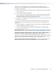

1. Cut the cables to the required length. Both cables should be the same length.
2. Remove about 7/8 inch (2.2 cm) of the outer coat. If using STP cable, peel back the
shielding and fold it over the top of the outer coat.
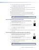
Peel back shield and
Fold back.
Figure 6. Terminating Cable (1)
3. Cut away and discard the clear cellophane inner wrapper that extends beyond the
folded back shielding.
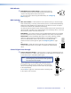
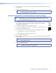
4. Cut a piece of self-adhesive shielded aluminum tape, remove the backing, and wrap
it around the folded back shielding. The tape should slightly overlap the end of the
shielding.
Aluminum Tape
Wrap tape around folded fo
il shielding.
(cut and save a portion for the
crimped connector tangs)
Figure 7. Terminating Cable (2)
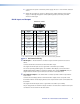
5. Separate the individual wires, and arrange them so that all eight wires are side by side
in the same order as the T586A or T586B standard shown below. Both ends of a cable
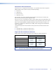
must be wired to the same standard (T586A or T586B).
Pin # TIA/EIA
T 586 A
Wire color
TIA/EIA
T 586 B
Wire color
Cable 1 Cable 2
1 White-green White-orange Data 0+ CEC
2 Green Orange Data 0- HPD
3 White-orange White-green ID Clock+ RS-232 Tx
4 Blue Blue Data 1+ DDC Clock
5 White-blue White-blue Data 1- +12 V
6 Orange Green ID Clock- RS-232 Rx
7 White-brown White-brown Data 2+ DDC Data
8 Brown Brown Data 2- Ground
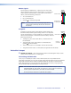
6. Feed the wires into the RJ-45 connector (see the figure above
right) and crimp the cable in the normal manner (see figure 7),
folding the tangs of the connector over the shielded tape.
Crimped Connector
Figure 8. Terminating Cable (3)
Side
12345678
Insert
Twisted
Pair Wires
Pins:
RJ-45
Connector
DVI 201xi Tx • Panel Features and Connections 8