
User Manual


2. Connect the AC power cord of the power supply unit to a 110 or 220 VAC electrical
source.
3. When the transmitter or receiver is getting power, either directly from the power
supply or indirectly through the remote powering feature, the front panel LED
shows an amber light.
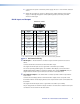
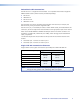
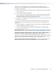
DVI-D Input and Output
Pin Signal
1
TMDS data 2–
TMDS data 2+
TMDS data 1–
TMDS data 1+
DDC clock +5 V power
DDC dat
aT
MDS clock+Ground
CEC control* TMDS clock–Hot plug detect
TMDS data 0–
TMDS data 0+
TMDS data
2 shield
TMDS data
1 shield
TMDS data
0 shield
TMDS clock
shield
Pin Pin Signal Signal
2
9
10
17
412
20
5
13
21
61422
71523
81624
18
31119
DVI Dual Link - Female
1
9
8
17 24
CEC control on pin 8 is a proprietary usage and is not the industry standard
Spare
Spare
Spare
Spare
Spare
Spare
*
Figure 5. DVI Connector Wiring
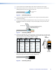
c DVI-D input — This female DVI-I connector accepts a DVI-D input from the source
device.
Connect the DVI-D source device to the female DVI-I input.
The single link DVI-D input carries a signal with a resolution up to 1080p.
For sources providing HDMI signals, use a HDMI to DVI adapter, such as the Extron
HDMIF-DVIDM female HDMI to male DVI-D adapter (Part number 26-616-01). The pin
assignments for the DVI-I input connectors are shown in the table above.
d Local monitor output — This female DVI-I connector provides a DVI-D output to the
local monitor.
Connect the local display device to the female DVI-I output on the rear panel of the
transmitter and the remote display device to the output of the receiver connected to the
transmitter.
The single link DVI-D output carries a signal with a resolution up to 1080p.
The pin assignments for the DVI-I output connectors are the same as those for the input
connections and are shown in the table above.
DVI 201xi Tx • Panel Features and Connections 5