User Guide DVI and HDMI® DVI 201xi Tx Single Link DVI Transmitter 68-1645-01 Rev.
Precautions Safety Instructions • English Warning This symbol is intended to alert the user of important operating and maintenance (servicing) instructions in the literature provided with the equipment. Power sources • This equipment should be operated only from the power source indicated on the product. This equipment is intended to be used with a main power system with a grounded (neutral) conductor. The third (grounding) pin is a safety feature, do not attempt to bypass or disable it.
FCC Class A Notice This equipment has been tested and found to comply with the limits for a Class A digital device, pursuant to part 15 of the FCC Rules. Operation is subject to the following two conditions: 1. This device may not cause harmful interference. 2. This device must accept any interference received, including interference that may cause undesired operation.
Contents Introduction............................................. 1 Mounting................................................. 18 About the DVI 201xi Tx..................................... 1 DVI 201xi Tx Features........................................ 1 Tabletop Mounting......................................... 18 Rack Mounting............................................... 18 Underwriters Laboratories Guidelines for Rack Mounting..................................... 18 Rack Mounting the DVI 201xi Tx..
DVI 201xi Tx • Contents vi
Introduction This guide contains information about the function, installation, and operation of the Extron® DVI 201xi Tx DVI transmitter. The guide also provides information about optional accessories that are available from Extron for the transmitter. In this manual, unless otherwise specified, the term transmitter and DVI 201xi Tx are used interchangeably.
Control communications pass-through — The DVI 201xi Tx passes through RS-232 (two way) or IR (one way) control signals, via the connected receiver, to a remote display. Compact design — The transmitter is 1U high, a half rack wide and 3 inches deep, for easy rack mounting near the source device. Remote powering of receiver — Pin 5 of twisted pair cable 2 carries a 12 VDC signal that allows the receiver to be powered from a single power supply connected to the transmitter.
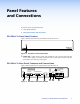
Panel Features and Connections This section of the user guide describes: zz Front panel features zz Rear panel features and connections DVI 201xi Tx Front Panel Feature Figure 2 (below) shows the front panel features of the DVI 201xi Tx. DVI 201xi Tx DVI TRANSMITTER 1 Figure 2. DVI 201xi Tx Front Panel Feature a Power LED — Lights amber to show when the DVI 201xi Tx is receiving power directly, from a power supply, or remotely, through the receiver.
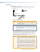
Power Input b Power input — The 12 VDC power supply (provided) connects to this two-pole, 3.5 mm captive screw connector. 1. Connect the captive screw connector from the power supply to the power receptacle. POWER 12V 0.4A MAX Power Receptacle Smooth A Ridges A SECTION A–A Power Supply Output Cord DC Power Cord Captive Screw Connector Ground +12 VDC AC Power Cord External Power Supply (12 VDC, 1 A ) Figure 4. Power Connections CAUTION: Power supply voltage polarity is critical.
2. Connect the AC power cord of the power supply unit to a 110 or 220 VAC electrical source. 3. When the transmitter or receiver is getting power, either directly from the power supply or indirectly through the remote powering feature, the front panel LED shows an amber light.
EDID Minder e EDID Minder Store switch and LED — When depressed, the EDID transmitter reads and stores the EDID information from the local monitor. The LED gives the status of this process. STORE For more information about using the EDID Minder, see Configuring EDID on page 10.
RS-232 signals RS-232 signals are bidirectional – signals pass from the control device and replies return from the remote device. To connect the control device to the transmitter or the receiver to the remote device, make the following connections: zz Tx is connected to Tx. zz Rx is connected to Rx. zz Ground ( ) is connected to ground. NOTE: For information about controlling display devices with RS-232 commands, see the user manual for that device.
1. Cut the cables to the required length. Both cables should be the same length. 2. Remove about 7/8 inch (2.2 cm) of the outer coat. If using STP cable, peel back the shielding and fold it over the top of the outer coat. Peel back shield and Fold back. Figure 6. Terminating Cable (1) 3. Cut away and discard the clear cellophane inner wrapper that extends beyond the folded back shielding. 4.
Twisted Pair Cable Connections The DVI 201xi Tx is a single link DVI transmitter. It is compatible with all Extron single link HDMI and DVI receivers (which must be purchased separately): zz DVI 201 Rx zz HDMI 201 Rx zz DVI 201 A D Rx zz HDMI 201 A D Rx The transmitter can also be used with appropriate dual link receivers (for example, the DVI DL 201 Rx), if they are used in single link mode.
Configuration and Operation This section of the user guide provides information about zz Configuring EDID zz Setup and Operation zz Troubleshooting Configuring EDID Using the EDID Minder to Read and Store EDID from a Display During boot up, the DVI-D source device uses Display Data Channel (DDC) to obtain Extended Display Identification Data (EDID) from the display device. This allows the output signal to match the resolution and refresh rate of the display device.
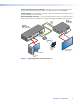
9. Connect the transmitter to the receiver with the two twisted pair cables: zz Transmitter port 1 connects to receiver port 1 zz Transmitter port 2 connects to receiver port 2 10. Power up the transmitter and the receiver. A single power supply can provide power to both units through the remote power connection. 11. Connect the remote display to the receiver output. A local monitor display can also be connected to the transmitter output at this time. 12.
6. Boot up the source device. The source boots with the resolution and refresh rate of the local monitor. 7. Power on the display device. NOTE: The remote display device must be capable of handling a resolution equal to or greater than that of the local monitor. Using Pass-through Mode with DDC Routed to the Remote Display NOTE: Although DDC can be routed to the remote display, there may be instances when the signals may become corrupted or weak.
Setup and Operation 1. Determine which display device will provide the EDID information and configure the DDC switches appropriately (see DDC Switches on page 6 and Configuring EDID on page 10). If necessary, use the EDID Minder to read and store information from a display (see Configuring EDID on page 10). 2. Prepare twisted pair cables (see Terminating shielded cable on page 7). 3.
DVI signals run at very high frequency and are especially susceptible to bad video connections, too many adapters, or cables that are too long. To avoid loss of an image or introduction of image jitter: zz The DVI cable on the input to the transmitter or the output from the receiver should not exceed 10 feet (3 m). zz Use only cable designed for DVI signals. zz Limit or avoid the use of adapters, patch panels, or couplers with the input DVI cables, the output DVI cables, and/or the twisted pair cables.
Specifications Video Maximum data rate ������������������������ 4.95 Gbps (1.65 Gbps per color) Maximum pixel clock ���������������������� 165 MHz Resolution range ���������������������������� Up to 1920x1200 or 1080p @ 60 Hz Formats ������������������������������������������ RGB and YCbCr digital video Standards ��������������������������������������� DVI 1.0, HDMI 1.
Serial control pin configuration ������� Captive screw connectors: 1 = TX, 2 = RX, 3 = GND General External power supply �������������������� 100 VAC to 240 VAC, 50-60 Hz, 6 W max., external; to 12 VDC, 2 A, regulated Power input requirements �������������� 12 VDC, 0.4 A for both transmitter and receiver NOTE: Each transmitter and receiver can be powered locally by an external power supply.
Reference Information This section of the user guide provides information about: zz Included Parts zz Compatible Receivers (must be purchased separately) zz Optional Accessories Included Parts Included parts Replacement part number (1) DVI 201xi Tx 60-1013-12 (1) 12 VDC, 1 A power supply 70-775-01 (4) Rubber feet (not attached) (2) 2-inch x 1-inch pre-cut Velcro® strips (1) 3-pole, 3.
Mounting This section describes the mounting options for the DVI 201xi Tx zz Tabletop Mounting zz Rack Mounting zz Under-desk Mounting Tabletop Mounting Attach the four provided rubber feet to the bottom of the unit and place it in any convenient location.
Extron® Warranty Extron Electronics warrants this product against defects in materials and workmanship for a period of three years from the date of purchase; touchscreen display and overlay components are covered for 1 year.
Installation Checklist Install the DVI 201xi Tx as follows: Step 1 — Configure the EDID:
Decide which display device will be used for the EDID information.
Configure the DDC switches (see DDC Switches on page 6 and Configuring EDID on page 10)
If necessary, use the EDID Minder to read and store information from a display (see Configuring EDID on page 10). Step 2 — Connect the transmitter to a receiver:
Prepare twisted pair cables (see Terminating shielded cable on page 7).