
User Guide Owner's manual


l
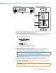
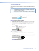
RS-232 (Control) Pass Thru connector — Connect a serial communications
port to this 3.5 mm, 3-pole captive screw connector for bidirectional RS-232
communication. See RS-232 connector wiring to wire the connector.
NOTE: The RS-232 connector can also transmit one-way modulated infrared (IR)
signals. See Modulated IR Pass Through Application.
m
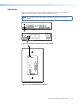
Audio output connector (DVI 201 A D Tx [Decora] only) — Connect a
stereo audio device to this 3.5 mm mini stereo jack to receive the unbalanced audio
output. Figure 15 on page 17 shows how to wire the audio plug.
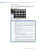
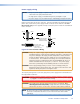
Pin Assignments and Wiring
DVI connector pin assignments
Figure 20 defines the pinout for the DVI protocol.
Pin Signal
1
TMDS data 2–
TMDS data 2+
TMDS data 1–
TMDS data 1+
DDC clock +5 V power
DDC data TMDS clock+ Ground (+5 V)
CEC control* TMDS clock– Hot Plug Detect
TMDS data 0–
TMDS data 0+
Spare
Spare
Spare
Spare
Spare
Spare
TMDS data 2
shield
TMDS data 1
shield
TMDS data 0
shield
TMDS clock
Shield
Pin Pin Signal Signal
2
9
10
17
4 12 20
5 13 21
6 14 22
7 15 23
8
* CEC control on pin 8 is a proprietary usage,
not the industry standard.
16 24
18
3 11 19
1
9
8
17 24
Female Connector
Male Connector
Figure 20. DVI Connectors
DVI 201 • Installation and Operation 21