
User Guide Owner's manual
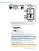


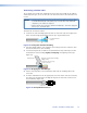


Connect the free ends of the same TP cables from the transmitter to the female Input
RJ-45 connectors (item
h
on page 20) on the receiver.
See TP cable termination to properly wire the RJ-45 connectors.
NOTES: • In order to fit in the junction box, the TP cables and RJ-45 connectors
should not have a boot installed.
• Extron recommends 28AWG to 24AWG TP cable for the RJ-45
connectors.
• For resolutions of 1600x1200, 1920x1200, and 1080p, Extron strongly
recommends DTP26 cable, or equivalent.
• Connect transmitter output 1 to receiver input 1. Connect transmitter
output 2 to receiver input 2.
• If necessary, test for proper cable connection (output 1 to input 1,
output 2 to input 2) as follows:
1
. Plug both TP cables into the powered unit.
2. Momentarily connect either of the cables on the opposite end into
the “2” connector on the unpowered unit.
If the Power LED on the unpowered unit is lit, the connection is
correct.
If the Power LED on the unpowered unit is not lit, unplug the
connector on the unpowered end and connect the other cable to
the “2” connector.
g
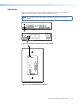
Audio Output connector (DVI 201 A D Tx [Decora] only) — Connect one
end of a 5-wire audio cable to this 3.5 mm, 5-pole direct insertion connector.
Connect the free end of the same cable from the transmitter to any compatibly wired
unit, such as a switcher, an amplifier, or a DVI 201 A D Rx (Decora) receiver (item
j
on page 20).
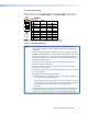
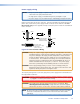
Figure 16 shows how to wire the captive screw audio connector. Insert the wires into
the appropriate openings in the direct insertion connector. Tighten the screws on the
side to fasten the wires.
Unbalanced Output Balanced Output
Do not tin the wires!
L
AUDIO
OUTPUT
R
Tip
Sleeve (s) Sleeve (s)
Tip
NO GROUND HERE.
NO GROUND HERE.
Tip
Tip
Ring
Ring
L
AUDIO
OUTPUT
R
Figure 16. Captive Screw Connector Wiring for Transmitter Audio Output
CAUTION: For unbalanced audio, connect the sleeves to the ground contact.
DO NOT connect the sleeves to the negative (-) contacts).
DVI 201 • Installation and Operation 18