User Guide DVI & HDMI Extenders DVI 201 DVI Twisted Pair Extender 68-1034-02 Rev.
Safety Instructions • English Warning This symbol is intended to alert the user of important operating and maintenance (servicing) instructions in the literature provided with the equipment. Power sources • This equipment should be operated only from the power source indicated on the product. This equipment is intended to be used with a main power system with a grounded (neutral) conductor. The third (grounding) pin is a safety feature, do not attempt to bypass or disable it.
FCC Class A Notice This equipment has been tested and found to comply with the limits for a Class A digital device, pursuant to part 15 of the FCC Rules. Operation is subject to the following two conditions: 1. This device may not cause harmful interference. 2. This device must accept any interference received, including interference that may cause undesired operation.
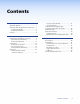
Contents Introduction............................................. 1 About this Manual............................................ 1 About the DVI 201 Transmitter and Receiver..... 1 TP Cable Advantages.................................... 3 Transmission Distance................................... 3 Features............................................................ 4 Installation and Operation...................... 5 Mounting the Transmitter or Receiver............... 5 Non-Decora Unit Mounting...........
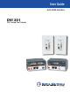
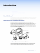
Introduction • About this Manual • About the DVI 201 Transmitter and Receiver • Features About this Manual This manual describes the Extron® DVI 201 family of Digital Visual Interface (DVI™) Extenders, which consists of DVI 201 Tx transmitters and DVI 201 Rx receivers. This manual describes how to install, operate, and configure them.
There are two subsets of transmitters and receivers in two different enclosures or form factors: • DVI 201 Tx/Rx — These units are housed in quarter rack width metal enclosures. They can be set on a tabletop or mounted in a rack, under or through furniture, or to a projector pole. The transmitter in this form factor has a local monitor output. NOTE: The non-Decora models do not input, transmit, receive, or output audio.
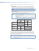
TP Cable Advantages Twisted pair cable is much smaller, lighter, more flexible, and less expensive than coaxial or DVI cable. These transmitter and receiver twisted pair (TP) products make cable runs simpler and less cumbersome. Termination of the cable with RJ-45 connectors is simple, quick, and economical. NOTES: • The transmitter and receiver pair works with unshielded twisted pair (UTP) or shielded twisted pair (STP) cables; but, to ensure FCC Class A and CE compliance, STP cables are required.
Features Transmits single link DVI-D signals over two CAT 5/5e/6 cables — Standard twisted pair cables provide an economical, easily installed cable solution. Local monitor output (DVI 201 Tx [non-Decora] only) — The DVI 201 Tx transmitter features a DVI-D output for connection to a local monitor. Supports DDC and HDCP copy protection transmission — The Tx/Rx pair fully supports long distance transmission of the DDC and HDCP signals.
Installation and Operation This section describes the installation and the operation of the DVI 201, including: • Mounting the Transmitter or Receiver • Connections • Operation • Technical Points for Digital Video and Contend Protection Encryption • Troubleshooting • Application Examples Mounting the Transmitter or Receiver CAUTION: Installation and service must be performed by authorized personnel only.
UL guidelines for rack mounting The following Underwriters Laboratories (UL) guidelines pertain to the installation of a DVI 201 unit onto a rack. 1. Elevated operating ambient — If installed in a closed or multi-unit rack assembly, the operating ambient temperature of the rack environment may be greater than room ambient. Therefore, consider installing the equipment in an environment compatible with the maximum ambient temperature specified by the manufacturer [Tma = +32 to +122 °F (0 to +50 °C)]. 2.
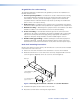
1U Universal Rack Shelf Figure 3. Mounting the Transmitter or Receiver on a Universal Rack Shelf Furniture mounting Under-furniture mounting The unit can be mounted under a horizontal surface using an optional MBU 125 underdesk mounting kit (part #70-077-01). Mount the unit under a desk or table as follows: 1. Remove feet from the bottom of the DVI 201 unit if installed. 2.
Through-furniture mounting The transmitter or receiver can be mounted through a desk or other furniture using an optional Extron MBD 129 through-desk mounting kit, part #70-077-02. Mount the transmitter or receiver through a desk or table as follows (figure 5): Figure 5. Through-Desk Mounting 1. Loosely attach the mounting brackets to the transmitter or receiver using the four machine screws and washers supplied with the mounting kit. 2.
Projector mounting The receiver can be mounted on a projector bracket using either of the following optional Extron projector mounting kits: • PMK 300 multi-product pole mount kit (part #70-374-01) • PMK 350 low profile, multi-product pole mount kit (part #70-563-02 [black] or part #70-563-03 [white]) PMK 300 mounting Mount the receiver to a PMK 300 bracket as follows: 1. If necessary, remove the feet from the bottom of the receiver. 2.
NOTE: The PMK 300 has a hole in the bottom plate that allows the projector pole to be inserted through the center of the plate (figure 7), rather than outside of the plate (figure 6). To install the PMK 300 in this configuration, slide the bracket up from the bottom of the pole before the projector is installed on the pole. Bracket Brace U-Bolt Extron PMK 300 Multi-product Pole Mount Kit Figure 7. Projector Pole on the Inside 4.
PMK 350 mounting Mount the receiver to a PMK 350 bracket as follows: 1. Remove the front and rear plates from the PMK 350 (figure 8), using an Extron Tweeker or a #2 Phillips screwdriver. Retain the screws to reattach the plates. Extron Quarter-rack Sized Product Rear Plate Contoured Base L-shaped Bracket Extron PMK 350 U-bolt Multi-product Pole Mount Kit Extron Power Supply Front Plate Cover Sheet Figure 8. PMK 350 Projector Mounting a Receiver 2.
7. Align the two slotted holes in the bottom of the L-shaped bracket with the two slotted holes in the base of the tray. Secure the L-shaped bracket to the base by inserting two provided 6-32 x 5/16-inch screws through the aligned slots. 8. Move the PMK 350 up to the desired location on the ceiling pole, as close to the ceiling as desired. 9. Secure the L-shaped bracket to the U-bolt using the included hex nuts, washers, and lock washers. Tighten the hex nuts securely.
Decora Unit Mounting The DVI 201 A D (Decora) transmitter and receiver can be installed in a one-gang electrical wall box with a Decora wall plate cover (supplied). The installation must conform to national and local electrical codes and to the size requirements of the wall plate. UL/safety guidelines The following Underwriters Laboratories (UL) guidelines pertain to the installation of the Decora transmitters and receivers into a wall or furniture. 1.
1. If a wall box is not available to use for a template, see the dimensions on page 35 to create a template. If installing directly into furniture, cut out the center portion of your template. 2. Place the wall box (or your template) against the installation surface, and mark the opening guidelines. 3. Cut out the material from the marked area. 4. Insert the wall box into the opening. The rear connectors on the box or wall plate should fit easily into the opening.
Final installation After testing and making any adjustments, do the following: 1. At the power outlet, unplug the power supply. NOTE: One power supply can power both the transmitter and the receiver, so only one unit needs a power supply. 2. Mount the transmitter or receiver into the wall box, and attach the supplied Decora faceplate to the unit, as shown in figure 12. Wall Box Decora Faceplate INPU T I DV Wall opening is flush with edge of box.
Connections Transmitter Connections The wall-mountable transmitter is in an enclosure that can be mounted in UL standard wall boxes with Decora-style face plates. The rack-mountable transmitter is in a quarter rack width enclosure. Figure 13 shows the front panel of the DVI 201 A D Tx. Figure 14, on the next page, shows the rear panel of both DVI 201 Tx models.
DVI 201 A D Tx Rear Panel DVI 201 Tx Rear Panel POWER 12V 0.4A MAX DVI 201 Tx DDC ROUTE REMOTE RS-232 PASS THRU SPARE LOCAL 5 1 2 Tx Rx 6 4 1 DVI 201 A D Tx 2 L POWER 5 DO NOT CONNECT TO LAN 12V 0.4A MAX 7 AUDIO OUTPUT R 6 O U T P U T S Figure 14. DVI 201 Tx Rear Panel Connectors c Audio input (DVI 201 A D Tx [Decora] only) — Connect an unbalanced stereo audio source to this 3.5 mm mini stereo jack for unbalanced audio input. Figure 15 shows how to wire the audio plug.
Connect the free ends of the same TP cables from the transmitter to the female Input RJ-45 connectors (item h on page 20) on the receiver. See TP cable termination to properly wire the RJ-45 connectors. NOTES: • In order to fit in the junction box, the TP cables and RJ-45 connectors should not have a boot installed. • Extron recommends 28AWG to 24AWG TP cable for the RJ-45 connectors. • For resolutions of 1600x1200, 1920x1200, and 1080p, Extron strongly recommends DTP26 cable, or equivalent.
Receiver Connections The rack-mountable receiver is in quarter rack width enclosure. The wall-mountable receiver is in an enclosure that can be mounted in UL standard wall boxes with Decorastyle face plates. Figure 17 shows the rear panel of both DVI 201 Rx models. Figure 18 shows the front panel of both DVI 201 Rx models. DVI 201 Rx Rear Panel POWER 12V 0.
h Receiver input ports — Connect one end of the two separate TP cables from the transmitter output connectors (item f on page 17) to these RJ-45 female connectors. CAUTION: Do not connect this device to a computer data or telecommunications network. Connect the free ends of the same TP cables from the receiver to the female Output RJ-45 connectors (item f on page 17) on the transmitter. See TP cable termination to properly wire the RJ-45 connectors.
l RS-232 (Control) Pass Thru connector — Connect a serial communications port to this 3.5 mm, 3-pole captive screw connector for bidirectional RS-232 communication. See RS-232 connector wiring to wire the connector. NOTE: The RS-232 connector can also transmit one-way modulated infrared (IR) signals. See Modulated IR Pass Through Application. m Audio output connector (DVI 201 A D Tx [Decora] only) — Connect a stereo audio device to this 3.5 mm mini stereo jack to receive the unbalanced audio output.
TP cable termination Figure 21 details the recommended termination of TP cables with RJ-45 connectors in accordance with either the TIA/EIA T 568A or the TIA/EIA T 568B wiring standard.
Terminating shielded cable The Tx and Rx each include two shielded RJ-45 connectors and a length of self-adhesive shielded tape that you can use to make the STP cables that connect the transmitter and receiver. NOTES: • The transmitter and receiver pair works with unshielded twisted pair (UTP) or shielded twisted pair (STP) cables; but, to ensure FCC Class A and CE compliance, STP cables are required. • Extron supplies the connectors and the shielded tape. You must supply the CAT 5, 5e, 6, or DTP26 cable.
Power supply wiring NOTES: • Only one power supply is required. A single power supply connected to either unit in the pair powers both units. • A single power supply is included with systems packaged as a pair. • A power supply is also included with each individually-packaged transmitter. Figure 25 shows how to wire the connector. Snap the provided ferrite bead onto the DC power cable, between the power supply and the connector on the DVI unit.
RS-232 connector wiring Figure 26 shows how to wire the RS-232 connector for non-Decora and Decora units. Tx/Rx Pins Connected RS-232 Device Pins Rx Tx Ground Transmit pin on connected unit Receive pin on connected unit Figure 26. RS-232 Connector Wiring CAUTION: The length of the exposed (stripped) copper wires is important. The ideal length is 3/16 inch (5 mm). Longer bare wires can short together. Shorter wires are not as secure in the connectors and could be pulled out.
Operation Figure 27 shows the DDC control and power indicator on the non-Decora transmitter. Figure 28 shows the power indicator on the Decora transmitter. NOTE: All transmitter and receiver models have power indicators in the locations shown. DVI INPUT LOCAL OUTPUT DVI 200 Tx SERIES DVI 201 Tx Transmitter Front Panel 1 POWER 12V 0.4A MAX DVI 201 Tx DDC ROUTE REMOTE RS-232 PASS THRU SPARE 1 LOCAL 2 Tx Rx DVI 201 Tx Transmitter Rear Panel 2 Figure 27.
Transmitter DDC Control and Power Indicator a Power LED — DVI 201 Tx (non-Decora) — This front panel LED lights green to indicate that the unit is receiving power: DVI 201 A D Tx (Decora) — This two-color front panel LED lights to indicate signal and power status as follows: Amber — The unit is receiving power but not a DVI input. Green — The unit is receiving power and a signal is present on the DVI input.
Technical Points for Digital Video and Content Protection Encryption • Digital Visual Interface (DVI) is a digital video format that was created by the computer industry in 1999. • High Definition Multimedia Interface (HDMI®) is a multimedia format that was created by the consumer video industry in 2003. оо The HDMI format is built onto the DVI format, adding digital audio and control while reducing the size of the connector. оо The HDMI format is likely to replace the DVI format in the near future.
Application Examples Audio Conversion Figure 29 shows a standard installation with DVI video and an audio input. The DVI 201 A D Tx converts the video input into two proprietary TP outputs. The Tx outputs the audio directly on a captive screw connector. Audio INPUT DVI AUDIO L+R RS-232 PASS THRU Source Rx Tx DVI-D In DVI 201 A D Tx Front O U T P U T S DVI 201 A D Tx 1 TP 2 2 Projector TP 1 POWER 12V 0.
Reference Information This section discusses the specifications, part numbers, and accessories for the DVI 201. Topics that are covered, include: • Specifications • Part Numbers • Decora Template Dimensions Specifications NOTES: • This product consists of a transmitter (DVI 201 Tx or DVI 201 A D Tx) and a receiver (DVI 201 Rx or DVI 201 A D Rx) with twisted pair cables linking the transmitter and receiver. • *Appropriate DVI-D to HDMI cables or adapters are required for HDMI signal input/output.
Video output— receivers Number/signal type ��������������������� 1 single link DVI-D (or HDMI*) Connectors DVI 201 Rx ������������������������� 2 female DVI-I DVI 201 A D Rx ������������������ 2 female DVI-I Audio— DVI 201 A D Tx/Rx Gain ������������������������������������������������� Frequency response ���������������������� THD + Noise ���������������������������������� S/N �������������������������������������������������� Stereo channel separation ������������ Unbalanced output: 0 dB; balanced outpu
Control/remote — external device (pass-through) Serial control port input Transmitter ������������������������� Receiver ������������������������������ Serial control port output Transmitter ������������������������� Receiver ������������������������������ RS-232 via (1) 3.5 mm, 3 pole captive screw connector 1 set of proprietary signals on a female RJ-45 jack 1 set of proprietary signals on a female RJ-45 jack RS-232 via a 3.
MTBF ����������������������������������������������� 30,000 hours Warranty ����������������������������������������� 3 years parts and labor NOTE: All nominal levels are at ±10%. NOTE: Specifications are subject to change without notice. Part Numbers Transmitter/Receiver Pair Part Numbers NOTE: The Tx/Rx is comprised of the transmitter and receiver pair. The transmitter and receiver can be purchased as a pair or separately.
Mounting Accessories Included parts Part number RSF 123 3-inch deep 1U rack shelf kit 60-190-20 RSB 123 3-inch deep 1U rack shelf 60-604-21 RSU 126 6-inch deep 1U universal rack shelf kit 60-190-10 RSB 126 6-inch deep 1U basic rack shelf 60-604-11 RSU 129 9.5-inch deep 1U universal rack shelf kit 60-190-01 RSB 129 9.
Decora Template Dimensions If you need to create a template, use the dimensions shown on figure 31, below. NOTE: The drawing is not full size or to scale. Do not scale up or print to use as a template. 2.79" (7.09 cm) Top Panel 1.9" (4.83 cm) 4.50" (11.43 cm) 2.8" (7.1 cm) SURFACE CUT-OUT AREA FOR FURNITURE MOUNT To install a 1-gang DVI 201 A D Tx or DVI 201 A D Rx directly into furniture or wall, cut along this line. Figure 31.
Extron Warranty Extron Electronics warrants this product against defects in materials and workmanship for a period of three years from the date of purchase.