
User Guide User Manual

DVI 104 TX/RX • User Guide
3
Rear Panel Features
Male Connector
13 68
17 19 22 249
3
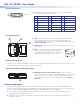
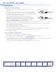
c A single-link DVI-D male connector is used to connect the transmitter to the
source and the receiver to the output device.
Pin Signal Pin Signal Pin Signal
1 TMDS data 2- 9 TMDS data 1- 17 TMDS data 0-
2 TMDS data 2+ 10 TMDS data 1+ 18 TMDS data 0+
3 TMDS data 2
shield
11 TMDS data 1
shield
19 TMDS data 0
shield
6 DDC clock 14 +5 V power 22 TMDS clock shield
7 DDC data 15 Ground (+5V) 23 TMDS clock+
8 CEC control 16 Hot plug detect 24 TMDD clock -
Top Panel Features
4 5
6
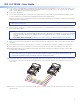
d LED — Both the transmitter and receiver have LEDs on the top and bottom
panels that light green when the unit is receiving power. The LEDs on the
transmitter also functions as a status indicator for the EDID minder feature (see
“Setup and Operation” below).
e Thumbscrews — Use the thumbscrews to secure the transmitter or receiver
to its connector.
f Label — a label in this space on the top panel identifies
33-1641-01
Rev. A 05 08
5 V 1234
Extron
www.extron.com
TO COMPUTER (Tx)
PN 60-977-12
the unit as the transmitter (Tx in the figure at right) or
receiver (Rx) and also identifies the power input (5 VDC)
and the fiber optic port numbers (1, 2, 3, and 4).
Bottom Panel Features
The bottom panels of both the transmitter and receiver have a label that identifies the serial number of the unit. There is also a second
power LED that mirrors the signals given by the LED on the top panel.
Side Panel Features (Transmitter Only)
7
g EDID Minder storage button (transmitter only) — A recessed switch
activates the transmitter to capture and store EDID information from the display
device. This allows the source device to provide a signal with a resolution
and refresh rate matching the needs of the display device (see “Setup and
Operation” ).
Setup and Operation
When using the DVI 104 Tx/Rx for the first time or if the display device is changed, it is essential to set up the EDID Minder. The
setup process places EDID information on a EEPROM chip in the transmitter, which allows the video source to boot up correctly. This
process is described below in steps 1-6. If you have already set up the EDID Minder, proceed to step 7.
1. Ensure that the source, the display, the transmitter, and the receiver are all powered off and that the fiber optic cables are
unplugged from the transmitter and the receiver.
2. Apply power to the transmitter by inserting the cable from the external power supply into the input jack. The LEDs should
illuminate a solid green.