
User's Manual Owner's manual

4-3
DVCM 50 • Special Application
PRELIMINARY
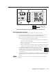
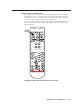
Connecting the DVCM 50 to the MLC 104
The DVCM 50 has a 3-pole RS-232 connector on the rear panel that is used to
connect the DVCM to the MLC 104. Connect a cable from the DVCM’s 3-pole host
port to the MLC 104’s host confi guration port as described below.
1. Cut the required length of Extron Comm-Link 3-wire cable to go between the
MLC 104 and the DVCM 50.
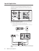
2. Using the diagram below as a guide, attach the provided 3.5 mm, 3-pole
captive screw connector to one end of the cable, and attach the other end of
the cable to the MLC 104 Host Confi g direct insertion captive screw connector.
The wires should be connected as follows:
DVCM Gnd to MLC Ground
DVCM Tx to MLC Rx
DVCM Rx to MLC Tx
The wire connecting the MLC 104 to the DVCM 50 should not exceed 25 feet.
3. Plug the 3-pole connector into the DVCM’s 3-pole host port on the rear panel.
Connectors are included with the DVCM 50, but the cable must be purchased
separately. See appendix A for cable part numbers.
1
1
2
3
8421
E
4
ON
234
IR OUT
GND
IR IN
GND
+ 12V
GND
Rx
Tx
+V
G
SCP
+12V OUT
PWR SNS
GROUND
GROUND
GROUND
GROUND
GROUND
Tx
Rx
HOST/
CONFIG
LAN
PRESS TAB WITH
TWEEKER TO REMOVE
A B
A B E
MLS/ PWR
RS-232
SCP
COMM
Tx/IR
Rx
Tx
Rx
+12V IN
MLC 104 side view
DVCM 50 rear view
Connecting the DVCM 50 to the MLC 104
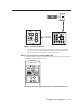
Input Selection
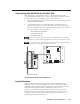
Whichever input the MLC 104 is using, DVD or VCR, the DVCM 50 is in the
equivalent mode. Conversely, whichever mode (DVD or VCR) the DVCM 50 is
in, the MLC 104 is using the corresponding input. (For example, if the MLC 104 is
using the DVD input, the DVCM 50 is in DVD mode, and vice versa.)
For this to occur, the MLC 104 and DVCM 50 must be connected as shown in
the illustration above, and the buttons must be confi gured correctly (see Setting
up buttons for DVD and VCR selection, on the next page, for information on
programming the MLC 104’s buttons).
•
•
•