
User's Manual Owner's manual

Installation, cont’d
DVCM 50 • Installation
2-8
PRELIMINARY
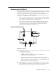
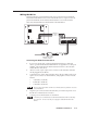
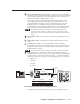
Wiring the power connector
The control connector also contains a power connector for the DVCM 50. You
can connect the optional external 12 VDC power supply to this port to power the
DVCM as shown in the following diagram.
The power supply is not included with the control module. The DVCM 50 can
share power with an MLC 104 or MLC 52.
Ground ( )
+12 VDC input
DVCM 50
Control
Port
E D C B A
A
B
Ground all devices.
An external
power supply
(12 VDC, 1A max.)
(Sold separately;
Part #70-055-01)
Connecting the DVCM 50 to the external power supply
Check the power supply’s polarity before connecting it to the DVCM.