
User's Manual Owner's manual

Installation, cont’d
DVCM 50 • Installation
2-6
PRELIMINARY
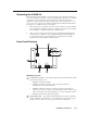
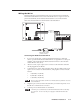
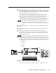
3. Attach a 3.5 mm, 5-pole captive screw connector to each end of the cable.
Only three wires are required:
• A (DVCM) to A (IR Link)
• B (DVCM) to B (IR Link)
• C (DVCM) to D (IR Link)
4. Connect the wires as shown in the illustration below. Connectors are included
with the IR Link, but the cable must be purchased separately.
5. Plug one 5-pole connector into one of the IR Link’s communications
connectors.
6. Plug the other 5-pole connector into the rear panel control port of the
DVCM 50.
IR Link (Rear Panel)
DVCM 50 (Rear Panel)
1
1
2
3
8421
E
4
ON
234
IR OUT
GND
IR IN
GND
+ 12V
GND
Rx
Tx
GND
+12V
A
B
D
GND
+12 V
A
B
C
IR IN
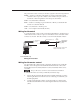
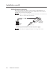
Wiring the IR Link for IR 452 remote control
Connect a maximum of one IR Link or IRL 20 to the DVCM 50.