
User's Manual Owner's manual

Installation, cont’d
DVCM 50 • Installation
2-4
PRELIMINARY
3
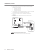
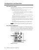
IR Learning indicator LEDs — Each button on the DVCM 50 front panel
has four memory blocks, which can be programmed with up to four IR
commands. The IR Learning indicator LEDs provide visual feedback,
indicating the following:
• Which of the four memory blocks contains a command
• Which of the four memory blocks is ready to be programmed or
confi gured.
• The IR Learning status of the control module
4
Button Indicator LEDs — These LEDs light in various patterns to indicate
which button on the front panel has been pressed when the DVCM is in
learning mode (confi guration switch #1 is in On position).
5
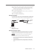
Control and power connector — This fi ve-pole, 3.5 mm captive screw
connector is used for IR control of the DVD and VCR, and for DC power. (See
Wiring the Control Connector, later in this chapter, for information on how to
connect supported devices to this connector.)
6
MLC 104 communication port — This 3.5 mm, 3-pole captive screw
connector, located near the lower-left corner of the rear panel, is used for
connecting to the MLC 104 (see chapter 4, Special Application, for more
information on the MLC 104). When the DVCM is operating in standalone
mode, this port is not used.
7
IR Learner/Transmitter LEDs — The two LEDs (one for transmitting, one
for receiving) send and receive IR signals, enabling the DVCM to learn
commands and clone confi gurations from another DVCM. (See chapter 3 for
more details.)
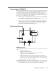
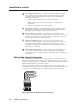
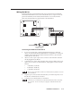
Wiring the Control Connector
Before mounting the DVCM 50 on the wall or furniture, you need to connect all
cable wires to the appropriate connector pins on the DVCM rear panel. Use cable
clamps to hold cables in place for strain relief. Trim back or insulate exposed cable
shields with heat shrink to prevent short circuits.
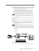
The control connector contains ports to which you can connect cables for IR-
controlled devices and AC power. The illustration below shows the DVCM control
connector’s pin assignments that are covered in detail on the following pages.
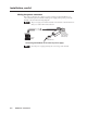
IR in
+12V
E D C B A
IR out
(IR)
(+12V)
Pinout guide for the DVCM 50 control connector