
User's Manual Owner's manual

2-3
DVCM 50 • Installation
PRELIMINARY
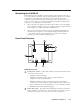
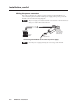
Mounting the DVCM 50
The DVCM 50 must be attached to a device faceplate, such as the MLC 104 AAP, or
to an AAP wallplate, such as the AAP 102, and cabled before the device or wallplate
is installed in a wall or furniture. The DVCM can be mounted in any Extron
wallplate or faceplate that can hold four single-space AAPs, arranged in two rows
of two AAPs each. The screws needed for installing the DVCM 50 are built into its
front panel, so no additional screws are needed.
1. Before any cables are attached, insert the control module’s screws through the
holes in the device faceplate or the AAP wallplate. Secure the control module
to the faceplate or wallplate with the provided hardware.
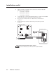
2. After you have connected all cables and programmed the DVCM’s buttons,
mount the device faceplate or AAP wallplate with the DVCM attached onto
a wall, electrical wall box, mounting bracket, or furniture, following the
instructions provided with the mounting option.
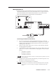
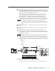
Rear Panel Features
5
4
1
1
2
3
8 4 2 1
E
4
ON
2 3 4
IR OUT
GND
IR IN
GND
+ 12V
GND
Rx
Tx
1
7
6
3
2
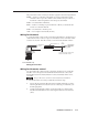
DVCM 50 rear panel
1
Confi guration switches — These DIP switches place the DVCM in IR learning
mode or data transfer mode.
• Switch 1: Enables IR learning.
• Switch 2: Enables data transfer, such as cloning the DVCM’s
confi guration onto another DVCM 50.
• Switch 3: When this switch is placed in On position, commands are
issued only once when a button is pressed and held. If the switch is set to
Off, its commands are issued repeatedly for as long as the button is held.
Switch 4: Enables MLC 104 input mapping.
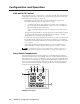
2
Enable Macro LED — The LED located immediately above the four green IR
LEDs is labeled E, for Enable Macro. This LED lights orange when you place
a button in macro mode. (See Setting up button macros, in chapter 3.)
•