Quick Start Guide DVCM 50 DVD/VCR Control Module 68-1208-01 Rev.
Precautions Safety Instructions • English Warning This symbol is intended to alert the user of important operating and maintenance (servicing) instructions in the literature provided with the equipment. Power sources • This equipment should be operated only from the power source indicated on the product. This equipment is intended to be used with a main power system with a grounded (neutral) conductor. The third (grounding) pin is a safety feature, do not attempt to bypass or disable it.
DVCM 50 Control Module Quick Start Guide The DVCM 50 DVD/VCR Control Module is a four-space Architectural Adapter Plate (AAP) module that is used for controlling DVDs and VCRs. It can be used with an MLC 52 or MLC 104 MediaLink Controller, or as a standalone control module, sending IR signals directly to the DVD or VCR.
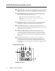
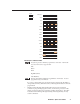
PRELIMINARY DVCM 50 Quick Start Guide, cont’d 2 Enable Macro LED — The LED located immediately above the four green IR LEDs is labeled E, for Enable Macro. This LED lights orange when you place a button in macro mode. (See Setting up button macros, later in this guide.) 3 IR learning indicator LEDs — Each front panel button has four memory blocks, which can be programmed with up to four IR commands.
1 DVD and VCR (mode selection) buttons — Use these buttons to switch the DVCM 50 operating mode between DVD and VCR. After one of these buttons is pressed, the DVCM buttons issue commands that control only the device with which the button is labeled (DVD or VCR). 2 DVD indicator LED — This LED glows amber when the DVCM is in DVD mode. 3 VCR indicator LED — This LED glows amber when the DVCM is in VCR mode. 4 Tx (Transmission) LED — This green LED blinks while the DVCM is transmitting IR commands.
DVCM 50 Quick Start Guide, cont’d Menu — (DVD mode only) Program this button with the IR command that displays the DVD menu on your display device. This button can be programmed and can issue IR commands only in DVD mode. Tuner W and X — (DVD mode only) Program these buttons with the IR command that moves the cursor right or left on the screen in order to select menu items or function icons. These buttons can be programmed and can issue IR commands only in DVD mode.
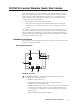
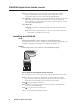
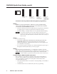
a. Wire the IR control port. To control the DVD or VCR via IR, connect Extron IR Emitters to the IR Out port of the DVCM control connector. Up to two IR emitters can be connected via this connector at one time. Wire the connector as shown in the following illustration. White striped wire only IR Emitter E Modulated IR D Ground Connect up to 2 IR Emitters (max.). 100 feet (33.5 m) maximum DVCM 50 IR control port Connect this end to the IR control window of the DVD or VCR .
DVCM 50 Quick Start Guide, cont’d Configuring the DVCM 50 The DVCM 50 can be programmed using the following methods: • IR learning from your DVD or VCR remote control • IR data transfer from another DVCM 50 that has been configured previously • Using DVD/VCR drivers with the MLC 52/DVCM 50 Windows®-based configuration software. Configuring using IR learning You can configure the DVCM 50 by using IR learning, which does not require configuration software.
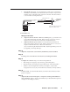
Legend OFF No Buttons ON DVD VCR UP TITLE MENU LEFT RIGHT ENTER PRELIMINARY TV/VCR DOWN REW PLAY FWD PAUSE STOP Button press indicator LEDs The following buttons cannot be programmed in VCR mode. The DVCM must be in DVD mode to program them. Title Menu Enter Right X (Tuner) Left W (Tuner) The TV/VCR button cannot be programmed in DVD mode. It can be programmed only in VCR mode.
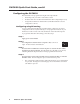
DVCM 50 Quick Start Guide, cont’d E E E E LED Off 4 4 4 4 LED Blinking 3 3 3 3 2 2 2 2 1 1 1 1 LED On Command 1 ready to be learned Command 2 ready to be learned Command 1 learned Command 3 ready to be learned.
Setting up button macros DVCM 50 buttons function in either toggle mode or macro mode. By default, the buttons are in toggle mode, which means that each press of the button initiates one of the commands saved to the button (each button can store up to four commands). In macro mode, a single press of a button issues all the commands (up to four) that have been programmed on that button, in the order they were programmed, at 1.5-second intervals. 1. Ensure that power is applied to the DVCM 50. 2.
DVCM 50 Quick Start Guide, cont’d 4. Verify that the button’s commands were erased by pressing the button again. If the commands have been erased, only LED #1 (the bottom LED) blinks; and the other LEDs are off. 5. Repeat steps 1 through 3 for any additional buttons that you want to erase. When finished, place switch #1 in the Off position (down).
The data transfer begins when the receiving unit detects the transmitting unit, and the process takes 15 to 20 seconds to complete. (It may take longer if the transmitting unit has multiple commands programmed on each button.) The button indicator LEDs on the rear panel act as data transfer progress indicators. While data is being transferred, these LEDs on both DVCMs light to indicate the amount of data that has been transferred.
DVCM 50 Quick Start Guide, cont’d Configuring using the Windows-based configuration software The DVCM 50 can be remotely configured via a host computer connected to the front panel configuration port. Through this port, you can program the DVCM’s buttons with commands by using the Windows-based configuration software (DVCM 50/DVCM 50 Control Program). The optional 9-pin D to 2.5 mm stereo mini TRS RS-232 cable (part #70-335-01) can be used for this connection.
The installation process has two parts: installing the software and installing the IP (IR) drivers. The files you will install need approximately 32 MB (megabytes) of total of hard disk space. To install the software and IR drivers onto the PC hard drive, follow these steps. Step 1 Insert the CD ROM into your CD drive. The disk should start automatically. If it does not, run LAUNCH.EXE from the CD. Step 2 PRELIMINARY Click Install Program on the Software Installation screen.
DVCM 50 Quick Start Guide, cont’d Step 5 Follow the instructions on the InstallShield Wizard screens to complete the program installation. By default the installation creates a directory called “MediaLink” on the PC hard drive, and places the following two icons in it: • MediaLnk52.exe (MediaLink configuration program) • MediaLnk52.hlp (MediaLink Help program) Step 6 Return to the Software Installation screen, and click Extron IP Link Drivers.
FCC Class A Notice Note: This equipment has been tested and found to comply with the limits for a Class A digital device, pursuant to part 15 of the FCC Rules. These limits are designed to provide reasonable protection against harmful interference when the equipment is operated in a commercial environment. This equipment generates, uses and can radiate radio frequency energy and, if not installed and used in accordance with the instruction manual, may cause harmful interference to radio communications.
www.extron.com Extron Electronics, USA Extron Electronics, Europe Extron Electronics, Asia Extron Electronics, Japan 1230 South Lewis Street Anaheim, CA 92805 USA 714.491.1500 Fax 714.491.1517 Beeldschermweg 6C 3821 AH Amersfoort The Netherlands +31.33.453.4040 Fax +31.33.453.4050 135 Joo Seng Road, #04-01 PM Industrial Building Singapore 368363 +65.6383.4400 Fax +65.6383.4664 Kyodo Building 16 Ichibancho Chiyoda-ku, Tokyo 102-0082 Japan +81.3.3511.7655 Fax +81.3.3511.