
User guide
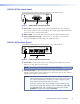
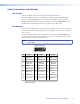
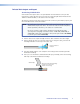
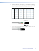
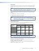
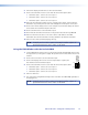
Table Of Contents
Cable Connections and Switches
DVI-D Input
Connect the DVI-D source device to the female DVI-I input connector.
The dual link DVI-D input carries a signal with a resolution up to 2560x1600 @ 60 Hz.
For sources providing HDMI signals, use an HDMI to DVI adapter, such as the Extron
HDMIF-DVIDM female HDMI to male DVI-D adapter (part number 26-616-01). The pin
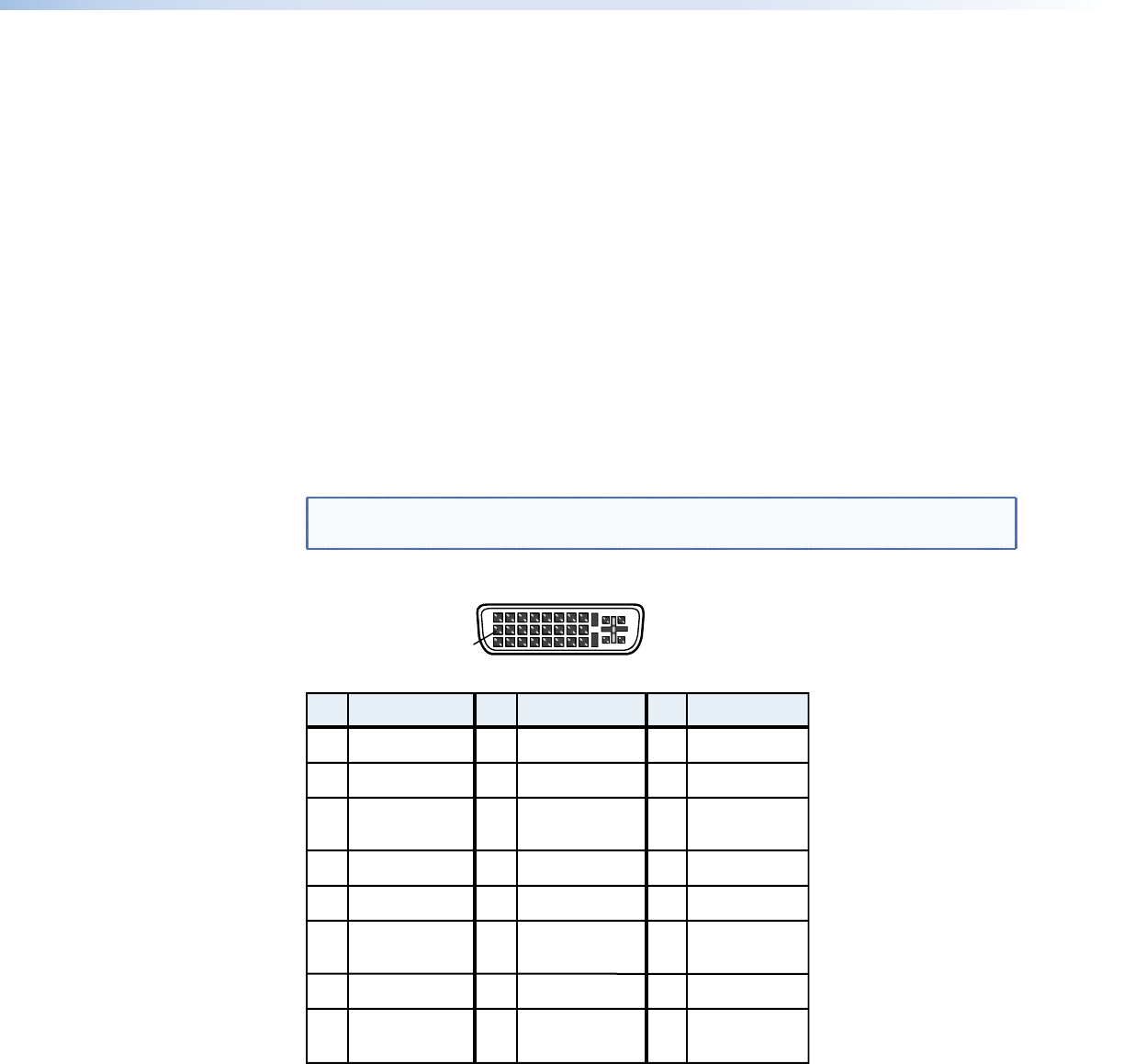
assignments for the DVI-I input connectors are shown in the table below.
DVI-D Output
Connect the local display device to the female DVI-I output connector on the rear panel of
the transmitter and the remote display device to the output connector on the front panel
of the receiver.
The dual link DVI-D output carries a signal with a resolution up to 2560x1600 @ 60 Hz.
The pin assignments for the DVI-I output connectors are the same as those for the input
connectors and are shown in the table below.
NOTE: Although DVI-I connectors are used, the DVI DL 201 is compatible only with
DVI-D signals.
Pin Signal
1
TMDS data 2–
TMDS data 2+
TMDS data 1–
TMDS data 1+
DDC clock +5 V power
DDC data TMDS clock+Ground
CEC control* TMDS clock–Hot plug detect
TMDS data 0–
TMDS data 0+
TMDS data 4-
TMDS data 4+
TMDS data 3-
TMDS data 3+
TMDS data 5-
TMDS data 5+
TMDS data
2/4 shield
TMDS data
1/3 shield
TMDS data
0/5 shield
TMDS clock
shield
Pin Pin Signal Signal
2
9
10
17
41
22
0
51
32
1
61
42
2
71
52
3
81
62
4
18
31
11
9
DVI Dual Link - Female
1
9
8
17 24
*CEC control on pin 8 is a proprietary usage and is not the
industry standard
DVI DL 201 Tx/Rx • Panels and Cabling 6