User Guide DVI Extenders DTP DVI 230 D DVI Twisted Pair Extender Transmitters and Receivers 68-2365-01 Rev.
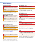
Safety Instructions Safety Instructions • English WARNING: This symbol, , when used on the product, is intended to alert the user of the presence of uninsulated dangerous voltage within the product’s enclosure that may present a risk of electric shock.
FCC Class A Notice This equipment has been tested and found to comply with the limits for a Class A digital device, pursuant to part 15 of the FCC rules. The Class A limits provide reasonable protection against harmful interference when the equipment is operated in a commercial environment. This equipment generates, uses, and can radiate radio frequency energy and, if not installed and used in accordance with the instruction manual, may cause harmful interference to radio communications.
Contents Introduction.................................................... 1 Reference Information................................ 15 About this Guide.................................................. 1 About the DTP DVI 230 D Extenders................... 1 Twisted Pair Cable Advantages........................ 2 Transmission Distance..................................... 2 Features.............................................................. 2 Decora Template Dimensions............................
Introduction • About this Guide • About the DTP DVI 230 D Extenders • Features About this Guide This guide describes the Extron DTP DVI 230 D family of Digital Visual Interface (DVI) Extenders, which consists of the DTP DVI 230 D Tx and DTP DVI 230 D Rx. This guide describes how to install, operate, and configure them.
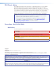
Twisted Pair Cable Advantages Twisted pair cable is much smaller, lighter, more flexible, and less expensive than coaxial or DVI cable. These transmitter and receiver twisted pair (TP) products make cable runs simpler and less cumbersome. Termination of the cable with RJ-45 connectors is simple, quick, and economical. NOTE: Do not use Extron UTP23SF-4 Enhanced Skew-Free AV UTP cable or STP201 cable to link the transmitter and receiver. The DTP HDMI 230 Tx/Rx does not work properly with these cables.
Installation and Operation This section describes the installation and the operation of the DTP DVI 230 D transmitter and receiver, including: • Mounting the Transmitter or Receiver • Transmitter Connections • Receiver Connections • Connector and Cable Details • Power Supply Wiring • RS-232 and IR Connector Wiring • Operation • Ground Loops Mounting the Transmitter or Receiver ATTENTION: Installation and service must be performed by experienced personnel.
To install a new wall box, perform steps 1 through 9. If a suitable wall box is already installed, perform steps 6 through 9 on the next page. UL listed wall boxes are recommended. 1. If a wall box is not available to use for a template, see Decora Template Dimensions on page 15 to create a template. If installing directly into furniture, cut out the center portion of your template. 2. Place the wall box (or your template) against the installation surface, and mark the opening guidelines. 3.
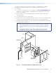
6. Feed the twisted pair cables and the power cables through the opening and through the wall box punch-out holes, securing them with cable clamps to provide strain relief. NOTES: • In order to fit in the junction box, the twisted pair cables and RJ-45 connectors should not have a boot installed. • One power supply can power both the transmitter and the receiver (see Power Supply Wiring on page 11 and Ground Loops on page 14). 7.
Final Installation After testing and making any adjustments, do the following: 1. At the power outlet, unplug the power supply. NOTE: One power supply can power both the transmitter and the receiver (see Power Supply Wiring on page 11 and Ground Loops on page 14). 2. Mount the transmitter or receiver into the wall box or mud ring, and attach the supplied Decora faceplate to the unit, as shown in figure 2 on page 4. 3. At the power outlet, reconnect the power supply. This powers up both units.
c Audio input — Connect an unbalanced stereo audio source to this 3.5 mm mini stereo jack for unbalanced audio input. Figure 5 shows how to wire the audio plug. Tip Left (+) Ring Right (-) Sleeve ( ) Figure 5. Audio Input Connector Wiring d RS-232 and IR (Control) pass-through connector — Connect a serial communications port to this 3.5 mm, 5-pole captive screw connector for bidirectional RS-232 communication and IR communication (see RS-232 and IR Connector Wiring on page 12 to wire the connector).
Connect the opposite end of the twisted pair cable to the receiver input port shown in figure 7 (see TP Cable Termination and Recommendations on page 10 to properly wire the RJ-45 connectors). NOTES: • In order to fit in the junction box, the twisted pair cables and RJ-45 connectors should not have a boot installed.
b DC power input connector — Plug the included external 12 VDC power supply into either this 2-pole connector or the power input connector on the receiver (see Power Supply Wiring on page 11 to wire the connector). Receiver Front Panel Figure 8 shows the front panel of the DTP DVI 230 D receiver. OUTPUTS DVI-D 1 OVER DTP RS-232 IR AUDIO 2 3 Tx Rx G Tx Rx Figure 8.
Connector and Cable Details TP Cable Termination and Recommendations Figure 9 details the recommended termination of both ends of TP cables with RJ-45 connectors in accordance with the TIA/EIA T 568B wiring standard. Pins: 12345678 TIA/EIA T 568 B Pin Wire color 1 White-orange 2 Orange 3 White-green 4 Blue 5 White-blue Green 6 TP Wires Figure 9.
Power Supply Wiring NOTES: • Only one power supply is required. A single power supply connected to either unit in the pair powers both units (see Ground Loops on page 14). • A power supply is included with each individually-packaged transmitter. Figure 10 shows how to wire the connector. Snap the provided ferrite bead onto the DC power cable, between the power supply and the connector on the DVI unit. 3/16" (5 mm) Max.
RS-232 and IR Connector Wiring Figure 11 shows how to wire the RS-232 and IR connector for the DTP DVI 230 D units. RS-232 Pin TX RX Gnd IR Tx Rx G Tx Rx Function Transmit data Receive data Signal ground IR Tx Rx G Tx Rx Controlling Device Do not tin the wires! Ground (G) Receive (Rx) Transmit (Tx) RS-232 Bidirectional Ground (G) Receive (Rx) Transmit (Tx) Do not tin the wires! Figure 11. RS-232 and IR Connector Wiring ATTENTION: The length of the exposed (stripped) copper wires is important.
Transmitter Power Indicator a Power LED — This two-color front panel LED lights to indicate signal and power status as follows: • Amber — The unit is receiving power but no signal on the DVI input. • Green — The unit is receiving power and a signal is present on the DVI input. Receiver Power Indicator b Power LED — This two-color front panel LED lights to indicate signal and power status as follows: • Amber — The unit is receiving power but no signal on the TP input.
Ground Loops When installing the DTP DVI 230 D series products, be sure to avoid scenarios where the ground potential differs greatly between the locations where the DTP transmitter and DTP receiver are installed. Such situations can cause ground loops, which can result in image drops, no image, or damage to the units. If such installations cannot be avoided, it is necessary to isolate the ground between the DTP transmitter and receiver.
Reference Information This section includes decora template dimensions for installation of the DTP DVI 230 D transmitters and receivers. Decora Template Dimensions If you need to create a template, use the dimensions shown on figure 14. NOTES: • The drawing is not full size or to scale. DO NOT scale up or print to use as a template. • Full size templates are available online at www.extron.com. Template for the 2-gang mounting bracket 4.26" (10.83 cm) 3.75" (9.53 cm) 4.28" (10.87 cm) 3.06" (7.
Extron Warranty Extron Electronics warrants this product against defects in materials and workmanship for a period of three years from the date of purchase.