
User Guide User guide


Operation
This section of the manual discusses the operation of an Annotator unit and is divided
into four sections:
• Front Panel Overview
• The Annotator Menu System
• Setting the Front Panel Locks (Executive Modes)
• Setting up the Annotator to Work with a Matrix Switcher
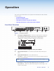
Front Panel Overview
ANNOTATOR
ANNOTATION GRAPHICS PROCESSOR
ADJUST
DETAIL
ZOOM
/PAN
BRIGHT
/CONT
COLOR
/TINT
SIZE
POSITION
UNDO
/CLEAR
CAPTURE
/RECALL
AUTO
IMAGE
FREEZE
6 754321
MENU
NEXT
INPUTS
1
2
5
3
4
6 7
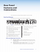
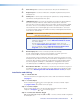
Figure 6. Front Panel Features
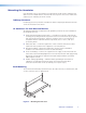
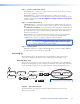
a Front panel configuration port — Connect a control system or computer to
this (RS-232) port using an optional 9-pin D to 2.5 mm mini jack TRS RS-232
cable, part 70-335-01 (see below). RS-232 protocol (default values):
• 9600 baud • 1 stop bit • no parity • 8 data bits • no ow control
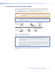
6 feet
5
1
9
6
Sleeve (Gnd)
Ring
Tip
9-pin D Connection TRS Plug
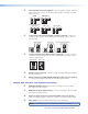
Pin 2 Computer Rx line Tip
Pin 3 Computer Tx line Ring
Pin 5 Computer's signal ground Sleeve
Figure 7. Front 2.5 mm Port Configuration Cable, Part 70-335-01
b Input selection buttons — Select/switch inputs and indicate which input is
active.
c Special function buttons — These four buttons are:
• Undo/Clear — Allows a reversal of up to seven of the last annotation points or
clears selected annotations.
NOTE: See the “On Screen Annotation” section for an overview of image
annotation.
• Auto Image — Initiates auto image adjustment on the selected input.
• Capture/Recall — Allows the capture and saving of the current image, or the
recall of a saved image.
Annotator • Operation 14