
User Guide User guide

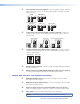
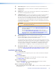
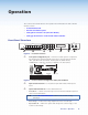

c Universal BNC connectors (input 3) — Connect a high resolution computer-
video, component, S-video, or composite input signal to this group of female
BNC connectors.
3
R/
R-Y
G/Y
VID
B/C
B-Y
H/HV V
RGsB/Component Video
(Y, R-Y, B-Y)
3
R/
R-Y
G/Y
VID
B/C
B-Y
H/HV V
3
R/
R-Y
G/Y
VID
B/C
B-Y
H/HV V
RGBHV
3
R/
R-Y
G/Y
VID
B/C
B-Y
H/HV V
Composite VideoS-video (YC)
RGBS/RGBcvS
3
R/
R-Y
G/Y
VID
B/C
B-Y
H/HV V
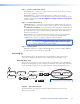
d Composite/S-video/component BNC connectors (input 4) — Connect a
composite video, S-video, or SD component video signal. Connect cables as
shown below.
Component Video (Y, R-Y, B-Y)
Composite Video
S-video (YC)
4
R-Y
B-Y
/C
VID
/Y
VID
/Y
4
R-Y
B-Y
/C
VID
/Y
4
R-Y
B-Y
/C
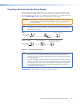
e S-video/composite video BNC connectors (input 5) — Connect S-video or
composite video input signals to this pair of female BNC connectors. Connect
cables as shown below.
5
VID
/Y
Composite Video
S-video (YC)
5
VID
/Y
C
C
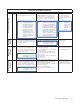
f DVI-D connector (input 6) — Connect a high resolution digital input signal to
this DVI-I connector.
g Optional input board (HD-SDI/SDI with BNC shown) connector (input 7)
— Connect an appropriate input to the optional board connector.
Output, User Interface, and Control Connections
h RGB/YUV-HD BNC connectors — Connect a display to these for RGB or
HD component video output.
i RGB/YUV-HD 15-pin VGA connector — Connect a display to this for RGB or
HD component video output.
j Optional output card (scan converter with BNC connectors shown) —
Connect a display to this for composite, S-video, or component video output.
k MTP output — Connect a mini twisted pair receiver to this port
NOTE: MTP output supports only RGBHV and RGBS video formats.
Annotator • Rear Panel Features and Connections
9