User Guide Signal Processors Annotator Annotation Graphics Processor 68-1661-01 Rev.
Precautions Safety Instructions • English Warning This symbol is intended to alert the user of important operating and maintenance (servicing) instructions in the literature provided with the equipment. Power sources • This equipment should be operated only from the power source indicated on the product. This equipment is intended to be used with a main power system with a grounded (neutral) conductor. The third (grounding) pin is a safety feature, do not attempt to bypass or disable it.
FCC Class A Notice This equipment has been tested and found to comply with the limits for a Class A digital device, pursuant to part 15 of the FCC Rules. Operation is subject to the following two conditions: 1. This device may not cause harmful interference. 2. This device must accept any interference received, including interference that may cause undesired operation.
Conventions Used in this Guide In this user guide, the following are used: NOTE: TIP: A note draws attention to important information. A tip provides a suggestion to make working with the application easier. CAUTION: WARNING: A caution indicates a potential hazard to equipment or data. A warning warns of things or actions that might cause injury, death, or other severe consequences.
Contents Introduction............................................. 1 About the Annotator........................................ 1 Definitions........................................................ 2 Features............................................................ 3 Installation............................................... 6 UL/Safety Requirements.................................... 6 Important Safety Instructions........................ 6 Mounting the Annotator..................................
Signal Processing Products Control Program...................... 61 Installing the Software.................................... 61 Installation From the DVD........................... 61 Installation from the Website...................... 62 Starting the SPPCP...................................... 62 Using the SPPCP............................................. 63 Orientation................................................. 63 SPPCP Menus.............................................. 64 Control Tab..........
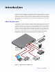
Introduction This manual contains installation, configuration, and operating information for the Extron Annotator. It covers configuring and operating the device using the front panel controls and Simple Instruction Set (SIS™) commands, and how to annotate the displayed image. It also describes how to load and start up the Windows®-based Signal Processing Products Control Program (SPPCP) and how to connect to the built-in HTML pages, for operating the processor.
Definitions The following terms are used throughout this manual: EDID — Extended Display Identification Data. A communications protocol or instruction set developed by VESA (Video Electronics Standards Association) for the identification of display devices to computers using the DDC (Display Data Channel) transmission standard. DVI — Digital Visual Interface. The digital video connectivity standard that was developed by DDWG (Digital Display Working Group).
Features • Real time annotations over high resolution PC and video graphics — This allows a presenter to draw, point, or add text in real time over live video and computer-video presentations. • Inputs: Two RGB or HD component video on 15-pin HD connectors; configurable input on BNC connectors for RGB, HD/SD component video, S-video, or composite video; component video, S-video, or composite video on BNCs; S-video or composite video on BNCs; DVI-D; and optional SDI/HD-SDI.
• Optional DVI, HD-SDI, or scan-converted output — A flexible output expansion port which can be populated to support optional DVI, HD-SDI, or scan converter output boards. These boards serve as a third Program output and offer additional system capabilities, such as recording or digital signal transmission. • Output rates — A total of 81 output rates are available, including computer-video rates up to 1920x1200, and HDTV rates up to 1080p/60 Hz.
• RS-232 serial control port — Using serial commands, the Annotator can be controlled and configured via the Extron Windows-based control program (SPPCP), or integrated into third-party control systems. Extron products use the SIS (Simple Instruction Set) command protocol, a set of basic ASCII code commands that allow for quick and easy programming.
Installation This section contains installation information for the Extron Annotator. It covers the following subjects: • UL/Safety Requirements • Mounting the Annotator UL/Safety Requirements The Underwriters Laboratories (UL) requirements listed below pertain to the safe installation and operation of this Annotation Graphics Processor. Important Safety Instructions 1. Read these instructions. 2. Keep these instructions. 3. Heed all warnings. 4. Follow all instructions. 5.
Mounting the Annotator If the Annotator is to be rack mounted, it is important to mount it before cabling it. Four rubber feet are included with the unit. Install the feet only if the unit is to be mounted on a table top (see “Tabletop placement” below). Tabletop Placement For tabletop placement, install the self-adhesive rubber feet/pads (provided) onto the four corners of the bottom of the device.
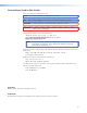
Rear Panel Features and Connections This section describes the rear panel features and how to connect the cables. Rear Panel Features The illustration below shows the rear panel features of the Annotator.
c Universal BNC connectors (input 3) — Connect a high resolution computervideo, component, S-video, or composite input signal to this group of female BNC connectors.
l PS/2 mouse port — Connect a PS/2 mouse to this port for annotation use. m Keyboard port — Connect a Microsoft® compatible keyboard to this port for annotation use. n USB A ports — Connect up to twenty touch panel devices (using USB hubs), or a USB mouse and keyboard to these ports. o LAN Ethernet port — Connect the Annotator to an Ethernet LAN or WAN via this RJ-45 connector. Ethernet control allows the operator to control the processor from a remote location.
Step 5 — Connect touch panel devices Via USB A ports — Connect a touchpanel device to either port as desired. For most devices no configuration is needed. Via RS-232 ports — Connect a touchpanel device to either port as desired. RS-232 driver configuration is necessary and can be done using the Signal Processing Products Control Program. See the “Signal Processing Products Control Program” section for details.
Resetting the Unit with the Reset Button There are four reset modes (numbered 1, 3, 4, and 5 for the sake of comparison with Extron IPL products) that you can access by pressing the Reset button on the rear panel. The Reset button is recessed, so use a pointed stylus, ballpoint pen, or Extron Tweeker to press it. See the table on page 13 for a summary of the reset modes. CAUTION: The reset modes listed in the table close all open IP and Telnet connections and close all sockets.
Annotator Reset Mode Summary Mode Run/Stop Events Use Factory Firmware 1 Hold down the recessed Reset button while applying power to the unit NOTE: 3 Reset all IP Settings 4 Reset to Factory Defaults Activation Purpose/Notes The Annotator reverts to the factory default firmware. Event scripting does not start if the device is powered in this mode. All user files and settings (drivers, adjustments, IP settings) are maintained.
Operation This section of the manual discusses the operation of an Annotator unit and is divided into four sections: • Front Panel Overview • The Annotator Menu System • Setting the Front Panel Locks (Executive Modes) • Setting up the Annotator to Work with a Matrix Switcher Front Panel Overview ADJUST INPUTS 1 2 3 4 5 6 UNDO /CLEAR AUTO IMAGE SIZE BRIGHT /CONT DETAIL MENU CAPTURE /RECALL FREEZE POSITION COLOR /TINT ZOOM /PAN NEXT 7 ANNOTATOR ANNOTATION GRAPHICS PROCESSOR 2 1
Freeze — Allows the current displayed image to be frozen or unfrozen as desired. • d Picture control buttons — These six buttons are: • Size — Allows adjustment to the displayed image size. • Bright/Cont — Allows adjustment of the brightness and contrast settings for the displayed image. • Detail — Allows adjustment of the detail (sharpness) settings for the displayed image. • Position — Allows horizontal and/or vertical position adjustment of the displayed image.
The Annotator Menu System The Annotator can be configured using the menu system, via the Extron Simple Instruction Set (SIS) of commands, or via the Extron Signal Processing Products Control Program (SPPCP) software program, through an RS-232 or LAN connected PC. NOTE: For methods see “SIS Communication and Control” and “Signal Processing Products Control Program” section.
Edit Comm Settings (hidden) To display and enter this menu, press and hold the Detail and Color/Tint buttons simultaneously and then press Next. The hidden menu appears. This menu allows the user to edit the following serial and IP settings: Serial port baud rate, DHCP mode, IP address, subnet mask, and gateway address. Exit Menu At this menu pressing Next exits the menu system and returns to the default cycle. User Presets Menu Next Input Configuration Menu Resol 1024x768 Refresh 60.
Scan Converter Configuration This menu, displayed only when the optional scan-converter board is installed, allows the user to configure the settings for scan-converted outputs. Aux Scaler Configuration This menu, displayed only when the optional aux scaler board is installed, allows the user to configure the settings for aux scaler outputs. Using the Menus To configure the Annotator using any of the menus, do the following: 1. Press the Menu button repeatedly to reach the desired configuration menu. 2.
Input Configuration Within this menu any of the seven inputs can be configured. Each input has different settings depending on the signal format. Consult the tables below for signal formats per input and possible adjustments per signal format. To configure inputs: 1. From the top level Input Configuration menu press the Next button to bring up the input selection screen. The active input is displayed on the LCD with current signal format.
Output Configuration Using this menu, resolutions, refresh rates, output signal types, and sync polarity can be selected and adjusted for an output. See the table below for resolution and refresh rates. 1. Press Next to bring up the Resolution submenu. In this submenu, the resolution and refresh rate can be adjusted. 2. Rotate the left front panel Adjust knob ([) to adjust the resolution value, and rotate the right Adjust knob ({) to adjust the refresh rate. Resolution 23.98 Hz 24 Hz 25 Hz 29.
Advanced Configuration Within this menu auto imaging and auto memory can be turned on or off, input EDID can be set, RGB delay value adjusted, the switch effect chosen, a test pattern selected to aid setting up the display, and the MTP pre-peaking turned on or off. In addition the internal temperature can be read, the touch panel display can be calibrated, and the unit can be reset to factory default settings. 1. Press Next to enter the first sublevel, Auto Image.
3. After tapping the fourth cross, the unit saves the calibration data and restarts the sequence. Repeat the process for each connected touchscreen. 4. Press any front panel button to exit the sequence and save the data. NOTE: See page 32 for detailed touchscreen setup instructions.
To recall an image: 1. Press and release the Capture/Recall button. The LCD displays “IMAGE RECALL”. 2. Press Next to enter the Recall menu. The LCD displays “Recall: ”. Use either Adjust knob to scroll through the saved images, to the desired image. 3. Press Next to recall the image. The LCD displays “Recalling image Please wait” while the image is downloaded to the display. When the image is fully downloaded, the LCD displays the name of the image and “Recalled”, (for example, “IMG05.bmp Recalled”).
Edit Comm Settings NOTES: • When entering this mode, the LCD menu displays the setting from comm port 1. Changes made to the comm settings via the front panel affects all the comm ports. • The lower rear panel RS-232 port is designated as Comm 1, the upper port is Comm 3, and the front panel config port is Comm 2. 1. Press Next to go through each sublevel to edit the following: serial port settings, DHCP (on or off), IP address, subnet mask, and gateway address.
Scan Converter Configuration This menu is available only when a scan converter board is installed. Within this menu horizontal and vertical image size and centering can be configured, output format and output standard chosen, and flicker, horizontal, and encoder filters set. 1. Press Next to enter the first sublevel, horizontal and vertical size. The current settings are displayed. (2048 is the default setting) 2.
Setting the Front Panel Locks (Executive Modes) The Annotator has two levels of front panel security lock that limit the operation of the device from the front panel. Executive mode 0 (disabled) — The front panel is fully unlocked. This is the default setting. Executive mode 1 (enabled) — The front panel is locked except for input switching, video freeze, and Auto Image. Executive mode 2 (enabled) — The front panel is completely locked. This mode can only be enabled and disabled using SIS commands.
Setting up the Annotator to Work with a Matrix Switcher The Sync to Matrix tool is a powerful tool which can simplify the control system necessary when using an Extron matrix switcher and an Annotator. The “Sync to Matrix” script can sense when a new tie that is made on the matrix is routed to the Annotator and automatically recalls the input preset associated with the input on the matrix switcher.
Input 1 Output 1 Input 3 Annotator #1 Output to display Input 2 Output 2 Input 3 Annotator #2 Output to display Input 3 Output 3 Input 4 Output 4 Input 5 Output 5 Input 3 Annotator #6 Output to display Input 6 Matrix Switcher Output 6 (optional) (optional) Output 3 Input 64 Output 4 Figure 17. Multiple Annotators Connected to a Matrix Switcher 3. On the Annotator, configure the input as follows: a. Switch to input 3 on the Annotator. b.
d. Click Connect to Matrix button. The matrix switcher size is displayed. e. From the drop-down menu next to Annotator Input #3. select the matrix output number that is connected to Input 3 on the Annotator. Click Take. The devices now sync. Figure 18. The Sync to Matrix Window NOTE: All other inputs on the Annotator must not be used when it is synchronized to a matrix switcher.
On Screen Annotation This section of the manual discusses on screen annotation and is in four sections: • USB and RS-232 Driver Configuration • USB Port Connections • Touchscreen Calibration • Annotation Overview The Annotator is a high performance, hardware-based annotation processor for video and computer-video sources. Annotating over motion video or still images is possible using common touchscreen panels, and a standard keyboard and/or mouse.
3. Select the USB Configuration tab and sort by device type, manufacturer, and version. 4. Click Update Modules to locate a device module in the Available Modules section 5. Select a module and click Add Module. The added module appears in the Loaded Modules on Annotator section. NOTE: Click Comm Sheet after selecting a device in the Available Modules section to see communication information for the selected device driver. To delete a touchpanel driver: 1.
Touchscreen Calibration If a touchscreen is attached to the Annotator, the touch accuracy should be calibrated using the Calibrate Panels setting in the Advanced configuration menu. Both RS-232 and USB connected touchscreens require calibration. To calibrate a connected and powered-on panel, do the following: 1. Press the Menu button on the front panel of the Annotator repeatedly until reaching the Advanced Configuration menu. 2.
Annotation Overview The Annotator output has the capability to include a graphical tool bar which is used for annotation. The tool bar can be enabled or disabled as desired. When enabled, the tool bar is visible down the right side of the display and allows selection of the following: Inputs selection, Pointer, Auto Image, Freehand, Line, Arrow, Rectangle, Ellipse, Text, Highlighter, Size select, Eraser, Color, Fill, Undo, Redo, Clear, Tools - Capture, Freeze, Mute, Whiteboard, Spotlight, Zoom, and Pan.
Default Annotation Buttons Input selection — Selecting this button opens a pop-up palette displaying the Annotator’s six inputs. Selecting any input button switches the display to that input. NOTE: A seventh input button (shown at right) is also displayed if an optional HD-SDI input board is installed. Pointer — Selecting this button changes the cursor to an extra-large arrow of the currently selected color.
Size — Select this button to adjust size of text and/or line weight (not linked), after selecting a drawing or text function, such as line, rectangle, or text. A secondary palette opens displaying either line weight or text point size depending on the active function. From the secondary palette select the desired size button. Functions this applies to are Text, Line, Arrow, Freehand, Highlighter, Arrows, Rectangle, Ellipse, and Eraser.
Whiteboard — Select this to create a white canvas for annotations. No input video image is visible. To remove the white canvas, reselect the Whiteboard button, select mute, or switch inputs. Spotlight — Select this to create an ellipse to focus on a specific area of the screen, while the outer area’s brightness is greatly reduced. The shape and size of the ellipse is adjustable by dragging the cursor while outside of it, to any point.
SIS Communication and Control The Annotator can be operated and configured using Simple Instruction Set (SIS) commands input via a PC connected to either of the processor’s serial ports or the Ethernet port. See o and p on pages 8 and 10, and “Ethernet Connection” section for wiring details. RS-232/RS-422 Link The Annotator has two rear ports and one front port that can be used for serial control. All ports enable use of SIS commands and the Windows-based control software.
Establishing a Connection Establish a network connection to the processor as follows: 1. Open a TCP socket to port 23 using the processor’s IP address. NOTE: If the local system administrators have not changed the value, the factoryspecified default, 192.168.254.254, is the correct value for this field. The processor responds with a copyright message including the date, the name of the product, firmware version, part number, and the current date/time.
Processor-Initiated Messages When a local event such as a front panel operation occurs, the processor responds by sending a message to the host. The processor-initiated messages are listed below. With an RS-232/422 connection (upon power up): (c) Copyright 2009, Extron Electronics Annotator, Vx.xx, 60-968-14] With an Internet connection: (c) Copyright 2009, Extron Electronics Annotator, Vx.xx, 60-968-14] Ddd, DD MMM YYYY HH:MM:SS (day, date time. for example.
Using the Command/Response Table for SIS Commands The command/response table follows this section. Lowercase letters are acceptable in the command field except where indicated. The table below shows the hexadecimal equivalent of ASCII characters used in the command/response tables. ASCII to HEX Conversion Table space • Figure 23. ASCII to Hexadecimal Conversion Symbols are used throughout the table to represent variables in the command/response fields.
X1@ = Internal temperature (in degrees Celsius) X1# = Horizontal and vertical frequencies (format is three digit with single decimal and leading zeros for example, 075.
X2% = User presets — 1 to 16 X2^ = Input presets — 1 to 128 X2* = On-screen menu time-out — 1 to 64, in 1 second increments, 0 = always displayed (default = 10) X3& = RGB delay — 0 to 50, in 0.1 second increments (default is 05 = 0.
Command ASCII command (host to processor) Response (processor to host) Additional description Input Switching and Configuration Input selection InX!] X!] Select video from input X!. View currently selected input source. X!*X#\ X!\ X!*\ TypX!*X#] Set input X! to video format X#. View video format of input X!. View actual video format auto detected on input X!.
Command/Response Table for SIS Commands Command ASCII command Response (host to processor) (processor to host) Specify a value EX^PHAS} PhasX!*X^] Increment value Decrement value View value E+PHAS} E-PHAS} EPHAS} PhasX!*X^] PhasX!*X^] Additional description Pixel phase X^] Set pixel phase to specified value for active input. Increase value. Decrease value. Show pixel phase.
Command ASCII command Response Additional description (host to processor) (processor to host) Mute video to black 1B Vmt1] Mute video to white 2B Vmt2] Unmute video View mode 0B B Vmt0] X4)] Mute video and display a black screen. Mute video and display a white screen. Restore picture. Mute status is X4). 1F 0F F Frz1] Frz0] Freeze selected input. Unfreeze selected input. X1)] Freeze status is X1). ColrX!*X1%] ColrX!*X1%] ColrX!*X1%] Set color level to X1%. Increase value.
Command ASCII command Response (host to processor) (processor to host) EX1^HCTR} E+HCTR} E-HCTR} EHCTR} HctrX!*X1^] HctrX!*X1^] HctrX!*X1^] Additional description Horizontal shift Specify a value Increment value Decrement value View value X1^] Set horizontal position to X1^. Shift position right. Shift image left. Show horizontal position value.
Command ASCII command Response Additional description (host to processor) (processor to host) Set output rate EX2!*X2@RATE} RateX2!*X2@] View output rate ERATE} X2!*X2@] Select output resolution and refresh rate. Show selected output rate. EX2#OPOL} EOPOL} OpolX2#] Set polarity for RGBHV ouput. X2#] Show current output polarity. OsynX2$] Set output sync format. X2$] Show current output sync format. VtpoX7%] Select video output format to X7%. X7%] View setting.
Command ASCII command (host to processor) Response (processor to host) Additional description Scan converter horizontal size HsizSX1&] HsizSX1&] HsizSX1&] Set horizontal size to X1&. Widen image. Make image narrower. X1&] Horizontal size is X1&. VsizSX1&] VsizSX1&] VsizSX1&] Set vertical size to X1&. Make image taller. Make image shorter. X1&] Vertical size is X1&. HdetSX7&] HdetSX7&] HdetSX7&] Set H filter level to X7&. Increase H filter level. Decrease H filter level.
Command ASCII command (host to processor) (processor to host) Response Additional description Set output rate EXX2!*X2@Rate} RateXX2!*X2@] Select output resolution and refresh rate. View output rate EXRate} X2!*X2@] Show selected output rate. Set polarity EXX2#OPOL} OpolXX2#] Set polarity for scaler ouput. View polarity setting EXOPOL} X2#] Show current output polarity. Set format EXX2$OSYN} OsynXX2$] Set output sync format.
Command ASCII command (host to processor) Response (processor to host) Additional description Advanced Configurations Test pattern EX2)TEST} ETEST} TestX2)] X2)] Select test pattern X2). View which test pattern is used. EX3&VDLY} EVDLY} VdlyX3&] X3&] Set RGB delay. View RGB delay setting. Cut Fade E0SWEF} E1SWEF} Swef0] Swef1] View setting ESWEF} 0] (or 1]) Sets the switch effect to cut. Sets the switch effect to fade through to black. View effect setting.
Command ASCII command Response Additional description (host to processor) (processor to host) EX5)DRAW} EDRAW} DrawX5)] DrawX5)] Sets current annotation to X5). View current annotation type. EX5&APNT} EASTP} (no response) Places the annotation location at X5&. Indicates the end of an annotation function.
Command ASCII command Response (host to processor) (processor to host) E1SHDW} E0SHDW} ESHDW} Shdw1] Shdw0] Additional description Drop shadow Enable drop shadow Disable drop shadow View setting X1)] Enable a drop shadow. Disable drop shadow. View current fill setting. ErsrX5$] Set the eraser/highlighter size to X5$. X5$] View current eraser/highlighter size. Clears all annotations on the output. Cannot be undone. Undoes the last annotation. Seven states are held in memory.
Command ASCII command (host to processor) Response (processor to host) Additional description On-Screen Menu Configuration Menu time-out Set menu time-out period EX2*MDUR} MdurX2*] View time-out EMDUR} MdurX2*] NOTE: Sets the menu duration to X2* seconds. View setting. Setting the time-out to zero disables the On-screen display (OSD) time-out. Menu display Set output to show menu E X@MSHW} MshwX@] View setting EMSHW} X@] NOTE: Sets which video outputs display the OSD. View setting.
Command ASCII command Response (host to processor) (processor to host) Erase user-supplied web pages and files Erase current directory and files Erase current directory and subdirectories Erase flash memory Reset all device settings to factory default settings Absolute system reset EfilenameEF} Del•filename] E/EF} Ddl] E//EF} Ddl] EZFFF} EZXXX} Zpf] Zpx] EZQQQ} Zpq] Absolute system reset (but retain IP) EZY} Zpy] Additional description Resets NOTE: Includes resetting IP to 192.168.254.
Using the Command/Response Table for IP SIS Commands Symbol Definitions X10) = Switcher name, up to 240 alphanumeric characters. NOTE: The following characters are invalid in the name: {space} ~ , _ @ = ` [ ] { } < > ‘ “ ; : | \ and ?.
X13& = Data bits: 7, 8 (default = 8) X13* = Stop bits: 1, 2 (default = 1) X13( = Serial port type: 0 = RS-232, 1 = RS-422 X14) = Flow control (only the first letter is needed): H = hardware, S = software, N = none X14! = Data pacing (time between bytes) in miliseconds, 0000 - 1000 (default = 0000 = 0 ms). X14@ = IP connection time-out period 1 - 65000, in 10‑second steps (default = 30 = 300 seconds). If no data is received during the specified period, the Ethernet connection closes.
Annotator • SIS Communication and Control 57 WX10@CT| WCT| WX10$CZ| WCZ| WX10%CX| WCX| WX10^CI| WCI| WCH| WCC| WX10^CS| WCS| WX10^CG| WCG| WX10(CA| WCA| W•CA| WX10(CU| WCU| W•CU| WX11^DH| WDH| E•CA} EX10(CU} ECU} E•CU} EX11^DH} EDH} Set subnet mask Read subnet mask Set gateway IP address Read gateway IP address Set administrator password Read administrator password Reset (clear) administrator password Set user password Read user password Reset (clear) user password Set DHCP on or off Read DHCP on/off s
Annotator • SIS Communication and Control 58 (tagged response in verbose mode 2/3) NOTE: WX12%%2AX12&%2AX13) %2AX13#%2AX13!CE| WX12%CE| EX12%CE} WX12%CF| WX12%%2AX14)%2CX14!CF| EX12%*X13%,X13^, X13&,X13*CP} EX12%CP} EX12%*X13(CY} EX12%CY} EX12%*X14),X14!CF} EX12%CF} EX12%*X12&*X13)* X13#*X13!CE} X12&,X13),X13#,X13!] X14),X14!] CpnX12%•CceX12&,X13),X13#, X13!] X13&,X13*] X13%,X13^,X13&,X13*] CpnX12%•CtyX13(] X13(] CpnX12%•CflX14),X14!] CpnX12%•CcpX13%,X13^, Ego] Est] X12# = Verbose mode: 0 = cle
Annotator • SIS Communication and Control 59 Epath/directory/CJ} Wpath/directory/%2FCJ| X14@] W1TC| Dir•path/directory/] Additional description NOTE: NOTE: X12% = specific serial port number (01-03), 01 = COM1 (rear panel, bottom port), 02 = COM2 (front panel config port), 03 = COM3 (rear panel, top port) X13! = Parameter (#L or #D) to set either the Length of message to receive or the Delimiter value. # = byte count (for L) or # = a single ASCII character expressed in decimal form (for D).
Annotator • SIS Communication and Control 60 WLF| Wfirst char in extensionLF| Wfirst char in filename first char in extensionLF| ELF} Efirst char in extensionLF} Efirst char in filename first char in extensionLF} List files from current directory and below List selected files from current directory and below List selected files from current directory and below Wfirst char in filename first char in extensionDF| Wfirst char in extensionDF| Efirst char in extensionDF} Efirst char in filename first ch
Signal Processing Products Control Program The Extron Signal Processing Products Control Program (SPPCP) offers another way to control the Annotator via RS-232 connection in addition to the SIS commands. This section describes SPPCP installation, communication, and control.
Installation from the Website 1. On the Extron website (www.extron.com), select the Download tab. 2. On the Download Center screen, select Software from the side-bar menu on the left. 3. Locate the Signal Processing Products Control Program file from the list and double click on it. 4. Follow the on-screen instructions to download the program to your PC. Starting the SPPCP 1. Click Start > Programs > Extron Electronics > Signal Processing > Signal Processing Products Control Program.
Using the SPPCP The Signal Processing Products Control Program (SPPCP) is used to configure and operate the Annotator from the PC on which the program resides. Orientation The SPPCP main window has 5 main tabs: Control, I/O Configuration, Advanced Settings, Image Capture, Font. A sixth tab appears only if a scan converter or an auxiliary scaler board is installed (aux scaler tab shown in figure 25). Click on each as desired. Figure 26.
SPPCP Menus File menu Click on this to open a drop-down menu displaying six selectable options: Connect, Disconnect, Save Configuration..., Restore Configuration..., File Manager, and Exit. • Connect — Select this to reconnect the Annotator (or connect a new device) when it has been disconnected from the Signal Processing Products Control Program. Follow the steps in the section “Starting the SPPCP.” • Disconnect — Select this to disconnect the unit from the Signal Processing Products Control Program.
Tools menu Click on this to open a drop-down box displaying nine selectable options: Data View/Trace Window... Executive Mode, Image Quick Capture..., On Screen Display, Device Module Configuration..., Sync Scaler to Matrix Switcher..., System Settings..., Reset, and Update Firmware.... • Data View/Trace Window...
• On Screen Display — Use this menu for a choice of two types of OSD: Default OSD and Custom OSD. Select as applicable. The Default OSD option is used to view the default OnScreen Display. The Custom OSD screen has two separate screens, Button OSD and Input OSD, which allow allows the user to customize the buttons and input names shown on the display. For complete instructions on how to customize the OSD, press , or click Help > Help. Figure 28.
Figure 30. The Device Module Manager Window: RS-232 Tab • Sync Scaler to Matrix Switcher — Select this to open a secondary window. Within that window enter the IP address of the matrix switcher that is connected to the Annotator. If required enter the password, then click Connect to Matrix. Select the output number from the Matrix Output to Annotator drop-down list and click Take. The Matrix Status section displays the matrix output that is being monitored and the tied input.
• System Settings... — Select this to open a secondary window. This allows changes to be made to various device settings: IP and RS-232 connections, date/time, and passwords. Select the applicable tab, change the settings as desired, and click Submit to make the changes effective. NOTE: • Changing the IP address may result in loss of connection to the LAN. • Only the baud rate can be changed when selecting the RS-232 tab. Figure 32.
To download and install the Firmware Loader application: 1. Go to www.extron.com. 2. Enter “Firmware Loader” in the Search field and press Enter. 3. Locate the Firmware Loader application in the results and click Download Now! 4. Follow the on-screen prompts to complete the download. To update the firmware: 1. From the SPPCP Tools menu, select Update Firmware. The SPPCP minimizes and the Firmware Loader application opens.
Figure 35. Firmware Loading Progress Window 5. When the file upload is complete (after file verification and the device restarting), click on the X at top right, or on File > Exit to exit the Firmware Loader. The SPPCP window restores itself. 6. Connection to the unit must be reestablished since the connection is lost during firmware upload. Open the SPPCP Connect dialog box and re-enter the connection information to re-establish communication with the Annotator.
Control Tab The Control tab displays the current configuration of the Annotator, with numbered boxes representing the video inputs. Also shown on the Control tab are the PIP control buttons, current picture adjustment values, input and user presets, as well as Video Mute, Freeze and Auto Image buttons.. Figure 37. The Control Tab Screen • Inputs — The current active input is shown (yellow). Select a desired input button to change to that input.
I/O Configuration Tab The I/O Configuration tab allows input and output configuration, as well as EDID emulation settings to be adjusted. Figure 38. The I/O Configuration Tab Screen • Input Config — Set a suitable video type for an input by clicking on the drop-down box (see input 7 above) and selecting a listed video type. If Auto Image on an input is desired mark the check box. Check Film Mode if 3:2 pull down detection for NTSC and 2:2 film detection for PAL video sources is relevant.
Advanced Settings Tab The Advanced Settings tab allows advanced functions to be configured. These include test pattern selection, and advanced features, used primarily during initial setup. Figure 39. The Advanced Settings Tab Screen • Test Pattern — Select any of the 14 test patterns to aid setting up an output display device. A small thumbnail of the pattern is shown on the tab (see above). Select Off where a test pattern is not needed.
Scan Converter Tab NOTE: The Scan Converter tab appears only if the optional scan converter output board is installed in the Annotator. The Scan Converter tab allows viewing and changing of the configuration settings of the optional scan converter output board. Figure 40. The Scan Converter Tab Screen • Picture Adjustments — The Picture Adjustments and Image Filter sections of the Scan Converter tab allows adjustments to be made to the image settings of the scan converted output.
Aux Scaler Tab NOTE: The Aux Scaler tab appears only if the optional aux scaler output board is installed in the Annotator. The Aux Scaler tab allows you to view and change the configuration settings of the optional Aux scaler output board. Figure 41. The Aux Scaler Tab Screen • Output Config — In this section the resolution, refresh rate, output type, and sync polarity can be set. The refresh rate selection is dependent on the resolution rate chosen.
Image Capture Tab The Image Capture tab allows capturing, saving, recalling, and deletion of displayed images. Figure 42. The Image Capture Tab Screen • Image Capture — Use this section to capture a displayed image to the Annotator internal memory. Enter a suitable name (maximum 12 characters) and click Capture. • Image Recall — Use this section to recall a captured image.
Font Tab The Font tab allows generation and selection of font type used by the Annotator. Figure 43. The Font Tab Screen • Font Generation — Use this to generate a font type to use by selecting from the font Type drop-down list and font style (regular or bold). Select the country whose font characters are to be used (United States, France, or Germany) and click Load. Enter a file name for the saved font file in the Save As dialog box and click Save.
HTML Operation This section describes these default web pages, which are always available and cannot be erased or overwritten. Topics that are covered include: • Accessing the Default Web Pages • Navigating the Default Web Pages Accessing the Default Web Pages Access the Annotator through the on-board web server pages as follows: 1. Double click the web browser icon on the PC desktop to launch the web browser. 2. Click in the browser’s Address field. 3.
Navigating the Default Web Pages The Annotator default web pages include five main tabs or pages (Status, Configuration, File Management, Control, and Images). These pages can be accessed at any time by clicking on the relevant tab. Some of the main pages have a series of sub-pages, accessible by clicking on the links in the sidebar menu allowing easy navigation of several administrative options including system settings, password control, file management, and device settings.
Configuration Tab The Configuration tab includes pages that allow System settings (such as IP address, date/time, and so forth), scaler settings, and passwords (admin and user), to be configured as desired. Additionally by selecting the Firmware Upgrade link the current firmware can be upgraded. If an optional board such as the Aux Scaler board has been installed a configuration page for the board will also be available.
DHCP radio buttons The DHCP On radio button directs the device to ignore any entered IP addresses and to obtain its IP address from a Dynamic Host Configuration Protocol (DHCP) server (if the network is DHCP capable). The DHCP Off radio button turns DHCP off. Contact the local system administrator to determine this control setting. IP Address The IP Address field contains the IP address of the Annotator. This value is encoded in the unit’s flash memory.
Date/Time Settings fields The Date/Time Settings fields provide a location for viewing and setting the time functions. Figure 46. Date/Time Settings fields Change the date and time settings as follows: 1. Click the desired variable’s drop-down box. The adjustable variables are month, day, year, hours, minutes, AM/PM, and (time) zone. A drop-down scroll box appears. 2. Click and drag the slider or click the scroll up variable is visible. or down buttons until the desired 3. Click on the desired variable.
Scaler Settings page Access the Scaler Settings page by clicking the Scaler Settings link on the sidebar menu on the Configuration page. Figure 47.
Output configuration Depending on the optional output card installed, the output connector and display device being used, the resolution and refresh rates can be set to one of various output rates from 640x480/50 Hz to 1920x1200, including HDTV 1080p/60 Hz. For a full table of output rates see page 20. The output sync format can be chosen from RGBHV, RGsB, YUV bi-or tri-level sync. Output polarity can be selected from H-/V- (default), H+/V-, H+/V+, or H-/V+.
On Screen Display Within this section, some aspects of the on screen display can be set. The annotation, cursor display can be set to be seen on all outputs, or where used, either group 1 or group 2 only, or on no outputs at all. The annotation menu display can also be set to be seen on all outputs, or where used, either group 1 or group 2 only, or on no outputs at all. In addition where the menu is to be displayed, the length of time the menu is visible can be set, the range being from 1.
Passwords page Access the Passwords page by clicking the Passwords link on the sidebar menu on Configuration page. Figure 50. Passwords Page The fields on the Passwords page are for entering and verifying administrator and user passwords. Passwords are case sensitive and are limited to 12 upper- and lowercase alphanumeric characters. Each password must be entered twice – once in the Password field and then again in the Re-enter Password field to the right.
Firmware Upgrade page Access the Firmware Upgrade page by clicking the Passwords link on the sidebar menu on Configuration page. The Firmware Upgrade page provides a way to replace the firmware that is coded on the Annotator control board without taking the processor out of service. Figure 51. Firmware Upgrade Page NOTE: The Firmware Upgrade page is only for replacing the firmware that controls all processor operation. To insert your own HTML pages, see “File Management” later.
Figure 52. Choose File to Upload Widow with a Firmware File Selected NOTES: • Valid firmware files must have the file extension “.S19”. Any other file extension is not a firmware upgrade. • The original factory-installed firmware is permanently available on the scaler. If the attempted firmware upload fails for any reason, the scaler automatically reverts to the factory-installed firmware. 7. Click Open. 8. Click Upload. While the firmware is uploading, the Upload button changes to “Uploading...” .
File Management Tab This tab shows the File Management page, and allows the user to upload or delete user files (such as HTML pages, or bitmaps) from the Annotator. To add or update files: 1. Select the File Management tab. The File Management screen is displayed. Figure 53. File Management Page NOTE: The files listed above are shown for example only. 2. Click the Browse button to locate the file(s) you want to upload.
Control Tab The three pages on the Control tab are User Control, Presets, and PIP Setup, and they allow limited device configuration. From the User Control page, the selection and viewing of inputs, mute and freeze selection, and execution of Auto Image is possible. Picture control and input sampling is also available on the User Control page. From the Presets page, up to 16 memory presets and up to 30 input presets can be saved and recalled.
Presets page From this page up to 16 memory or 128 input presets can be saved and recalled. Figure 55. Presets Page To save the current configuration to a memory or input preset, click on the applicable drop-down box, scroll to the desired preset number and click Save. To recall a memory or input preset as the current configuration, click on the applicable drop-down box, scroll to the desired preset number and click Recall. The current configuration is then replaced by the recalled configuration.
Images page This page allows images (.bmp format) to be added to or deleted from the Annotator, previewed, and recalled to be shown on a connected display device. Figure 57. Images Page To add an image, click Add, browse to the image location on the connected PC, and click Upload Image. The image is uploaded to the Annotator and a thumbnail of the image is viewable on the Images page (see the figure above). NOTE: The image is not yet displayed.
Reference Material This section provides information about: • Specifications • Part Numbers and Accessories Specifications Video input Number/signal type ������������������������ 2 RGBHV, RGBS, RGsB, component video (Y, R-Y, B-Y; progressive or HD) 1 RGBHV, RGBS, RGsB, component video (Y, R-Y, B-Y; interlaced, progressive, HD), S-video, composite video 1 component video (Y, R-Y, B-Y; interlaced), S-video, composite video 1 S-video, composite video 1 single link DVI-D 1 optional SDI, HD-SDI Connectors �
Video output Number/signal type ������������������������ 2 buffered scaled RGBHV, RGBS, RGsB, or HD component video (Y, R-Y, B-Y) 1 MTP 1 optional single link DVI-I (for unique scaled output); DVI-D; HD-SDI; or interlaced RGsB, component video, S-video, composite video Connectors ������������������������������������ 6 female BNC: RGB or component video 1 female 15-pin HD: RGB or component video 1 female RJ-45: output to an MTP device 1 slot for an optional output card with one of the following options: · 1
Web server ������������������������������������� Up to 200 simultaneous sessions 40 MB nonvolatile user memory Program control ����������������������������� Extron control/configuration program for Windows® Extron Simple Instruction Set (SIS™) Microsoft® Internet Explorer®, Telnet Control/remote — annotation Number/signal type ������������������������ 20 USB devices (via hubs) 2 serial devices 1 PS/2 mouse 1 PS/2 keyboard Connectors ������������������������������������ 2 USB type A 2 RS-232, female 9-pin
Part Numbers and Accessories Included Parts Description Part Number Annotator 60-968-xx Rubber feet (not attached) (4) IEC power cord (1) Extron Software Products DVD Setup guide Cables The cable listed below is for front panel RS-232 use. Description Part Number CFG 9-pin D female to 2.5 mm TRS configuration cable 70-335-01 NOTE: For signal cable requirements, please check the latest Extron catalog or visit www.extron.com for a comprehensive list.
Ethernet Connection This section describes connection to the Ethernet. Ethernet Link The rear panel Ethernet connector on the Annotator can be connected to an Ethernet LAN or WAN. This connection makes SIS or software control of the unit possible using a computer connected to the same LAN. Ethernet Connection The Ethernet cable can be terminated as a straight-through cable or a crossover cable and must be properly terminated for your application.
Ping to determine Extron IP address The ping utility is available at the command (Cmd) prompt. Ping tests the Ethernet interface between the computer and the Annotator. Ping can also be used to determine the actual numeric IP address from an alias and to determine the web address. Ping the device as follows: 1. From the Windows Start menu, select Run... . The Run window opens. 2. In the Open text field, enter command. 3. Click OK. A DOS command window opens. 4.
4. At the prompt, enter Telnet. The computer returns a display similar to the figure below. Figure 60. Telnet Screen Telnet Tips It is not the intention of this manual to detail all of the operations and functionality of Telnet; however, some basic level of understanding is necessary for operating the Annotator via Telnet. Connecting to the Annotator (Open command) You connect to the Annotator using the Open command.
Local echo Once your computer is connected to the Annotator, by default Telnet does not display your keystrokes on the screen. SIS commands are entered blindly, and only the SIS responses are displayed on the screen. To command Telnet to show all keystrokes, enter set local echo at the Telnet prompt before you open the connection to the processor. With local echo turned on, keystrokes and the processor’s responses are displayed on the same line.
IP addresses and octets Valid IP addresses consist of four 1-, 2-, or 3-digit numeric subfields, properly called octets, which are separated by dots (periods) (figure 61). Each octet can be numbered from 000 through 255. Leading zeros, up to 3 digits total per octet, are optional. Values of 256 and above are invalid. Typical IP Address: 192.168.254.254 Octets Figure 61.
Extron Warranty Extron Electronics warrants this product against defects in materials and workmanship for a period of three years from the date of purchase.