MVX Plus 128 VGA Matrix Switchers 68-521-30 Rev.
Precautions Safety Instructions • English Warning This symbol is intended to alert the user of important operating and maintenance (servicing) instructions in the literature provided with the equipment. Power sources • This equipment should be operated only from the power source indicated on the product. This equipment is intended to be used with a main power system with a grounded (neutral) conductor. The third (grounding) pin is a safety feature, do not attempt to bypass or disable it.
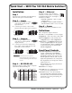
Quick Start — MVX Plus 128 VGA Matrix Switchers Step 5 — Ethernet Installation Step 1 Turn off power to the input and output devices, and remove the power cords from them. • Network connection — Wire as a patch (straight) cable. • Computer or control system connection — Wire the interface cable as a crossover cable. Step 2 — Inputs a. Connect up to 12 high resolution video inputs to the 15-pin HD input connectors. b. Connect up to 12 stereo or mono audio inputs to the 5-pin captive screw connectors.
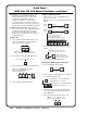
Quick Start — MVX Plus 128 VGA Matrix Switchers, continued Esc button cancels selections in progress and resets the front panel button indications. The Esc button does not reset: the current configuration, the RGBHV and audio selection, any presets, or any audio level or volume settings. On audio models, Esc increments the level and volume. See Viewing and adjusting the audio level in the next column. RGBHV and Audio buttons select/deselect video and/or audio.
Table of Contents Chapter One • Introduction ...................................................................................................... 1-1 About this Manual..................................................................................................................... 1-2 About the Matrix Switchers ................................................................................................ 1-2 Definitions ...............................................................................
Table of Contents, cont’d Viewing and adjusting the output volume ......................................................................... 3-33 Reading the displayed volume ......................................................................................... 3-34 Example 11: Viewing and adjusting an output volume level ......................................... 3-36 Locking out the front panel (Executive mode) ...................................................................
Chapter Five • Matrix Software ............................................................................................. 5-1 Matrix Switchers Control Program ................................................................................. 5-2 Ethernet protocol settings .................................................................................................. 5-2 Using the software...................................................................................................................
Table of Contents, cont’d Chapter 6 • HTML Operation ..................................................................................................... 6-1 Download the Startup Page ................................................................................................ 6-2 System Status Page .................................................................................................................. 6-3 DSVP page ..............................................................................
Appendix A • Ethernet Connection .................................................................................... A-1 Ethernet Link ............................................................................................................................... A-2 Ethernet connection ................................................................................................................ A-2 Default address ...........................................................................................
PRELIMINARY Table of Contents, cont’d 68-521-30 A 12 05 All trademarks mentioned in this manual are the properties of their respective owners.
1 Chapter One Introduction About this Manual About the Matrix Switchers Definitions Features PRELIMINARY MVX Plus 128 VGA Matrix Switchers
Installation About this Manual This manual contains installation, configuration, and operating information for the Extron MVX Plus 128 12-input by 8-output wideband computer video (VGA) and audio matrix switcher. About the Matrix Switchers The MVX matrix switcher distributes any of 12 inputs to any combination of 8 outputs. The matrix switcher can route multiple input/output configurations simultaneously.
The MVX Plus 128 inputs and outputs VGA video on 15-pin HD connectors and audio on 3.5 mm, 5-pole captive screw terminals. The audio switching can be either linked with the video (audio follow) or be independent of the video (audio breakaway). Adjustable input audio gain and attenuation compensates for level differences between audio inputs. The matrix switcher can be remotely controlled via its Ethernet port and its RS-232/RS-422 port.
Introduction, cont’d Features Video — The switchers input and output RGBHV or RGBS (VGA) video on 15-pin HD connectors. They can also switch RGsB, RsGsBs, component/ HDTV, S-video, or composite video. Bandwidth — The MVX switchers provide a minimum of 300 MHz (-3 dB) video bandwidth, fully loaded. Audio inputs — Input and output stereo audio, balanced or unbalanced, is provided on 3.5 mm, 5-pole captive screw terminals.
Rooming — Each switcher can be programmed to group multiple outputs to specific “rooms”, allowing them to have their own presets. • Tie any input to any or all outputs • Quick multiple tie — Multiple inputs can be switched to multiple outputs simultaneously. This allows all displays (outputs) to change from source to source at the same time. • Audio follow — Audio can be switched with its corresponding video input via front panel control or under Ethernet or RS-232/RS-422 remote control.
Introduction, cont’d Global memory presets — 32 global memory presets are a time-saving feature that lets you set up and store input/output configurations in advance. 20 global memory presets are available from the front panel. You can then recall those configurations, when needed, with a few simple steps. Rack mounting — Rack mountable in any conventional 19” wide rack.
2 Chapter Two Installation Mounting the Switcher Cabling and Rear Panel Views PRELIMINARY MVX Plus 128 VGA Matrix Switchers
Installation Mounting the Switcher The matrix switchers are housed in rack-mountable, 2U high metal enclosures with mounting flanges for standard 19” racks. If desired, rack mount the switcher as follows: 1. Insert the switcher into the rack, aligning the holes in the mounting bracket with those in the rack. 2. Secure the switcher to the rack using the supplied bolts. Cabling and Rear Panel Views All connectors are on the rear panel. Figure 2-1 shows the MVX Plus 128 A.
Audio connections By default, the audio ties follow the video ties. Audio breakaway, which can be activated via the front panel or under Ethernet or RS-232/RS-422 control, allows you to select from any one of the audio input sources and route it separately from its corresponding video source. See chapter 3, Operation, chapter 4, Programmer’s Guide, chapter 5, Switcher Software, and chapter 6, HTML Operation for details. c Connections for balanced and unbalanced audio inputs — Each input has a 3.
Installation, cont’d d Connections for balanced and unbalanced audio outputs — These 3.5 mm, 5-pole captive screw connectors output the selected unamplified, line level audio. Connect audio devices, such as an audio amplifier or powered speakers. See figure 2-4 to properly wire an output connector. Tip Ring Sleeve (s) Tip Ring Tip See caution Sleeve Tip See caution Unbalanced Output Balanced Output Figure 2-4 — Captive screw connector wiring for audio output C Connect the sleeve to ground (Gnd).
Ethernet connection Ethernet port — If desired, connect the matrix switcher to a PC or to an Ethernet LAN, via this RJ-45 connector. You can use a PC to control the networked switcher with SIS commands from anywhere in the world. You can also control the switcher from a PC that either is running Extron’s windows-based control program or has downloaded HTML pages from the switcher. Activity Link LED LED f Ethernet connection indicators — The Link and Act LEDs indicate the status of the Ethernet connection.
Installation, cont’d Patch (straight) cable Pin Side Clip Down Pins 1 2 3 4 5 6 7 8 RJ-45 connector Side 1 Wire color Pin Side 2 Wire color 1 White-orange 1 White-orange 2 Orange 2 Orange 3 White-green 3 White-green 4 Blue 4 Blue 5 White-blue 5 White-blue 6 Green 6 Green 7 White-brown 7 White-brown 8 Brown 8 Brown 12345678 Crossover cable Pin PRELIMINARY Twisted Pairs 1&2 7&8 3&6 4&5 Side 1 Wire color Pin Side 2 Wire color 1 White-orange 1 White-green 2 Or
3 Chapter Three Operation Front Panel Controls and Indicators Front Panel Operations Rear Panel Controls Optimizing the Audio Troubleshooting Configuration Worksheets PRELIMINARY MVX Plus 128 VGA Matrix Switchers
Operation Front Panel Controls and Indicators The front panel controls (figure 3-1) are grouped into two sets. The input and output buttons are grouped on the left side of the control panel. The control buttons and video/audio (I/O) selection buttons are grouped on the right side of the panel.
Input and output buttons N If the switcher has fewer inputs or outputs than input or output buttons, only the buttons for which the switcher has an input or output perform the function of selecting and identifying that input or output. b Input buttons — The input buttons have two primary functions (•) and four secondary (❏) functions: • Select an input. • Identify the selected input. ❏ (Input 1 only) With the Output 1 button, select I/O Group mode. See I/O grouping on page 3-17. ❏ Select a preset.
Operation, cont’d PRELIMINARY d e ❏ Select 9600 baud for the RS-232/RS-422 port in Serial Port Configuration mode. See Selecting the RS-232/RS-422 protocol and baud rate on page 3-40. ❏ Indicate that the RS-232/RS-422 port is set to 9600 baud in Serial Port Configuration mode. See Selecting the RS-232/RS-422 protocol and baud rate on page 3-40.
f Esc (>) button — The Esc (>) button has two primary functions (•) and eight secondary (❏) functions: • Cancel operations or selections in progress and reset the front panel button indicators. • Flashes once to indicate that the escape function has been activated. ❏ In the I/O Group mode, select group 4. See I/O grouping on page 3-17. ❏ In the I/O Group mode, indicate that group 4 is selected. See I/O grouping on page 3-17. ❏ Increase the RGB delay of switches to the selected output.
Operation, cont’d PRELIMINARY h Audio button — The Audio button has two primary functions (•) and three secondary (❏) functions • Selects and deselects audio for a configuration that is being created or viewed. • Lights to indicate that audio is available for configuration or viewing. ❏ Selects the Audio mode, in which you can adjust the input audio level and the output audio volume.
Front Panel Operations The following paragraphs detail the power-up process and then provide sample procedures for creating ties, changing a configuration, viewing configurations, saving and recalling a preset, muting and unmuting outputs, viewing and adjusting the audio level, viewing and adjusting the output volume, locking out the front panel, performing one of several resets, toggling background illumination on and off, and reading and setting the RS-232/RS-422 Remote port settings.
Operation, cont’d N • Only one video input and one audio input can be tied to an output. • If a tie is made between an input and an output, and the selected output was previously tied to another input, the older tie is broken in favor of the newer tie. • If an input with no tie is selected, only that input’s button lights.
4. Press and release the output 3, output 4, and output 8 buttons (figure 3-6). Press and release the Output 3, Output 4, and Output 8 buttons. The buttons blink amber to indicate that the selected RGBHV and audio input will be tied to these outputs. 1 2 3 4 5 6 7 8 CONTROL ENTER PRESET OUTPUTS VIEW ESC The Enter button blinks green to indicate the need to confirm the change.
Operation, cont’d Example 2: Adding a tie to a set of video and audio ties In the following example, a new video tie is added to the current configuration. The steps show the front panel indications that result from your action. N This example assumes that you have performed example 1. 1. Press and release the Esc button (figure 3-9). Press the Esc button to clear all selections. CONTROL ENTER PRESET VIEW ESC The button flashes once. Figure 3-9 — Clear all selections 2.
5. Press and release the Enter button (figure 3-13). Press the Enter button to confirm the configuration change. ENTER All input buttons and output buttons return to unlit or background illumination. The Enter button returns to unlit or background illumination.
Operation, cont’d Example 3: Removing a tie from a set of video and audio ties In the following example, an existing audio tie is removed from the current configuration. The steps show the front panel indications that result from your action. N This example assumes that you have performed example 1 and example 2. 1. Press and release the Esc button (figure 3-15). Press the Esc button to clear all selections. CONTROL ENTER PRESET VIEW ESC The button flashes once. Figure 3-15 — Clear all selections 2.
5. Press and release the Enter button (figure 3-19). Press the Enter button to confirm the configuration change. ENTER All input buttons and output buttons return to unlit or background illumination. The Enter button returns to unlit or background illumination.
Operation, cont’d Viewing a configuration The current configuration can be viewed using the front panel buttons. The View-Only mode prevents inadvertent changes to the current configuration. View-Only mode also provides a way to mute video and audio outputs (see Muting and unmuting video and/or audio outputs on page 3-26. View the current configuration as follows: 1. Press the Esc button to clear any input button indications, output button indications, or control button indications that may be on. 2.
Example 4: Viewing video and audio, audio only, and video only ties The following steps show an example of viewing the video and audio, audio-only, and video-only ties in the current configuration. The steps show the front panel indications that result from your action. N This example assumes that you have performed example 1, example 2, and example 3. 1. Press and release the Esc button (figure 3-21). Press the Esc button to clear all selections. CONTROL ENTER PRESET VIEW ESC The button flashes once.
Operation, cont’d N You can also view a set of ties by selecting a tied output. To demonstrate this, note the number of a lit output button, and then press and release the output button for an untied (unlit or background illumination) output. Observe that all of the untied outputs light. Then press the output button that you noted previously and observe that the selected output button, the tied input button (input 5), and the output buttons light for all of the outputs that are tied to the input. 5.
I/O grouping I/O grouping is a matrix switcher feature that allows you to subdivide the front panel control of the matrix into four smaller functional sub-switchers and limit tie creation from the front panel only. Inputs and outputs can be assigned to one of four groups or not assigned to any group. When you are creating ties on the front panel, inputs and outputs that are assigned to a group can be tied only to other outputs and inputs within the same group.
Operation, cont’d PRELIMINARY The I/O groups can be set up on the front panel or by using RS-232/RS-422 and Ethernet ports and either the SIS or the Windows control program (see chapter 4, Programmer’s Guide, and chapter 5, Matrix Software). Create I/O groups on the front panel as follows: 1. Press the Esc button to clear any input buttons, output buttons, or control buttons that may be lit. 2.
Example 5: Grouping inputs and outputs In the following an example, several switcher inputs and outputs are assigned to groups. The steps show the front panel indications that result from your action. 1. Press and release the Esc button (figure 3-28). Press the Esc button to clear all selections. CONTROL ENTER PRESET VIEW ESC The button flashes once.
Operation, cont’d 5. Press and release the Preset button to select group 2 (figure 3-32). Press and release the Preset button to select group 2. The button lights amber to indicate the selection. CONTROL ENTER PRESET Group # 1 2 VIEW ESC 3 4 Figure 3-32 — Select an I/O group 6. Press and release the input 5 through 8 and output 5 through 8 buttons (figure 3-33). Press and release the Input 5 through Input 8 buttons. The selected buttons light.
Setting RGB delay The switcher can briefly blank the RGB (video) output while it switches to the new input’s sync source, and then switches the RGB signals. This allows a brief delay for the display to adjust to the selected input’s sync timing before displaying the new picture, which then appears without glitches. RGB delay, also known as Triple-Action Switching or video mute switching, is user selectable from 0 to 5 seconds, in half-second increments. 1.
Operation, cont’d Press and hold the RGBHV button for approximately 2 seconds (figure 3-35). 2. RGBHV 2 seconds RGBHV Press and hold the RGBHV button until it blinks. = Blinking button Figure 3-35 — Select RGB Delay mode Press and release the output 17 button (figure 3-36). 3. The Input 1 through Input 10 buttons display the selected output's RGB delay. Each lit input button indicates half a second of delay. In this example, the green input buttons display 3.5 seconds of RGB delay. 0.
5. Press and release the RGBHV button (figure 3-38). Press the RGBHV button to exit RGB delay mode. I/O RGBHV AUDIO All input buttons and output buttons return to unlit or background illumination. The RGBHV button stops blinking and goes out or becomes background illuminated. The Audio button lights red. Figure 3-38 — Deselect RGB Delay mode The current configuration (configuration 0) can be saved as a preset in any one of 32 preset memory addresses.
Operation, cont’d Example 7: Saving a preset In the following example, the current configuration is saved as a preset. The steps show the front panel indications that result from your action. 1. Press and release the Esc button (figure 3-40). Press the Esc button to clear all selections. CONTROL ENTER PRESET VIEW ESC The button flashes once. Figure 3-40 — Clear all selections 2. Press and hold the Preset button for approximately 2 seconds until it blinks (figure 3-41).
4. Press and release the Enter button (figure 3-43). The current configuration is now stored in the selected memory location. Press the Enter button to save the preset. CONTROL ENTER PRESET VIEW ESC The Enter and Preset buttons return to unlit or background illumination. All input buttons and output buttons return to unlit or background illumination. Figure 3-43 — Press the Enter button Example 8: Recalling a preset In the following example, a preset is recalled to become the current configuration.
Operation, cont’d 4. Press and release the Enter button (figure 3-47). The configuration stored in the selected memory location is now the current configuration and can be viewed in the View-Only mode (see example 4). Press the Enter button to recall the preset. CONTROL ENTER PRESET VIEW ESC The Enter and Preset buttons return to unlit or background illumination. All input buttons and output buttons return to unlit or background illumination.
Example 9: Muting and unmuting an output In the following example, several switcher outputs are muted and unmuted. The steps show the front panel indications that result from your action. 1. Press and release the Esc button (figure 3-48). Press the Esc button to clear all selections. CONTROL ENTER PRESET VIEW ESC The button flashes once. 2. Press and release the View button to enter View-Only mode. The View button lights red. 3.
Operation, cont’d 4. One at a time, press and hold the Output 3 button and then the Output 4 button (figure 3-50) for approximately 2 seconds until each button begins to blink. The output 3 and output 4 video and audio signals are muted. Mute outputs one at a time. 3 2 seconds 3 Press and hold the Output 3 button. The button blinks amber to indicate that the RGBHV and audio outputs are muted. 4 2 seconds 4 Press and hold the Output 4 button.
6. Press and release the View button to exit View-Only mode (figure 3-52). Press the View button to exit View-Only mode. VIEW All input buttons and output buttons return to unlit or background illumination. The View button returns to unlit or background illumination.
Operation, cont’d N • Pressing the Enter or Preset button also exits Audio mode. Pressing the Preset button changes to Recall Preset mode. • There is one audio level setting per input. The audio level setting is shared by the left and right audio inputs. • The audio level settings are stored in non-volatile memory. When power is removed and restored, the audio level settings are retained.
Input audio level adjustment displays Indications 24 1 2 3 4 5 6 7 8 23 1 2 3 4 5 6 7 8F 22 1 2 3 4 5 6 7 8S 21 1 2 3 4 5 6 7 8 20 1 2 3 4 5 6 7F 8 19 1 2 3 4 5 6 7S 8 18 1 2 3 4 5 6 7 8 17 1 2 3 4 5 6F 7 8 16 1 2 3 4 5 6S 7 8 15 1 2 3 4 5 6 7 8 14 1 2 3 4 5F 6 7 8 13 1 2 3 4 5S 6 7 8 12 1 2 3 4 5 6 7 8 11 1 2 3 4F 5 6 7 8 10 1 2 3 4S 5 6 7 8 9 1 2 3 4 5 6 7 8 8 1 2 3F
Operation, cont’d 3. Press and release the Input 5 button (figure 3-56). Press and release the Input 5 button. The button lights green. INPUTS 1 2 3 4 5 6 7 8 9 Green Green Green 1 2 3F 4 5 6 7 8 OUTPUTS The output buttons display the selected input's audio level and polarity (gain or attenuation). Each button indicates: 1 dB when blinking slowly, 2 dB when blinking quickly, 3 dB when lit. When the buttons are lit green, they indicate a gain (+) audio level.
5. Press and release the Audio button (figure 3-58). Press the Audio button to exit audio mode. I/O RGBHV AUDIO All input buttons and output buttons return to unlit or background illumination. The Audio button stops blinking and lights red. The RGBHV button lights green. Figure 3-58 — Deselect Audio mode Viewing and adjusting the output volume 1. Press the Esc button to clear any input buttons, output buttons, or control buttons that may be lit. 2.
Operation, cont’d Reading the displayed volume N This section is a detailed look at reading the output volume display on the switcher’s front panel. If you do not need to read the exact value of the volume setting, skip this section. There are 65 steps of volume attenuation, with 1 dB per step (button push), except for 0-to-1, which is 35 dB. At maximum attenuation, no input buttons are lit, 98 dB of attenuation is applied, and the audio output is effectively muted.
Audio volume adjustment settings None 1 1 98 0% Slow blink 63 5.5% 62 7% Fast blink 61 8.5% 1 2 2 Slow blink Fast blink 2 3 3 4 5 58 13% 57 14.5% 56 16% 55 17.5% 54 19% 53 20.5% 52 22% 23.5% 50 25% 49 26.5% 48 28% 47 29.5% Slow blink 46 31% 45 32.5% 44 34% Fast blink 43 35.5% 42 37% 41 38.5% 40 40% 39 41.5% 38 43% 37 44.5% Fast blink 4 5 10% 11.5% 51 Slow blink 3 4 60 59 Slow blink Fast blink 5 36 46% 35 47.
Operation, cont’d Example 11: Viewing and adjusting an output volume level In the following example, the audio output volume is viewed and adjusted. The steps show the front panel indications that result from your action. 1. Press and release the Esc button (figure 3-59). Press the Esc button to clear all selections. CONTROL ENTER PRESET VIEW ESC The button flashes once. Figure 3-59 — Clear all selections 2. Press and hold the Audio button for approximately 2 seconds (figure 3-60).
Figure 3-62 show the result of pressing the Esc (>) button a total of 13 times. Press the Esc button to decrease the audio attenuation (thereby increasing the audio level) that is applied to the output volume level by 1 dB per button push. ESC –26 dB attenuation, 61% volume INPUTS 1 2 3 4 5 6 7F 8 9 10 11 12 The input buttons display the selected output's audio volume level. In this example, the green input buttons display 61 percent of the applied audio input.
Operation, cont’d Locking out the front panel (Executive mode) The front panel security lockout limits the operation of the switcher from the front panel. When the switcher is locked, all of the front panel functions are disabled except for the View-Only mode functions. See Viewing a configuration on page 3-14. Other than in View-Only mode, if the user pushes a front panel button when the switcher is locked, the RGBHV and Audio buttons flash twice and return to their previous state.
Background illumination The buttons on the front panel can be set to provide amber background illumination at all times or the background illumination can be turned off. To toggle the background illumination on or off, press and hold the Input 1 and Input 2 buttons simultaneously for approximately 2 seconds (figure 3-66). Press and hold the Input 1 and Input 2 buttons simultaneously to toggle background illumination mode on or off. 1 2 3 2 seconds Release the Input 1 1 2 3 and Input 2 buttons.
Operation, cont’d Selecting the RS-232/RS-422 protocol and baud rate The switcher can support either RS-232 or RS-422 serial communication protocol, and operate at 9600, 19200, 38400, and 115200 baud rates. The settings of these variables can be viewed and changed from the front panel. View and configure the switcher’s serial communications settings as follows: 1. To enter Serial Port Configuration mode, simultaneously press and hold all Control buttons (Enter, Preset, View, and Esc) (figure 3-67).
Rear Panel Controls The rear panel has a Reset button that initiates four levels of matrix switcher resets. Press and hold the button while the switcher is running or while you apply power to the switcher for different reset levels. Performing soft system resets • Events (mode 3) reset — This function toggles the monitoring of events on or off (if events monitoring was on, this function turns it off; if it was off, it is turned on).
Operation, cont’d Perform a soft reset of the switcher as follows: Press and hold the rear panel Reset button until the front panel RGBHV and Audio buttons blink once (events reset), twice (system reset), or three times (absolute reset) (figure 3-70). Release, then immediately press and release again. RGBHV AUDIO Buttons and Reset LED flash once. 1 Release, then immediately press and release again. PRELIMINARY RESET Press and hold the Reset button.
Performing a hard reset The hard reset function restores the switcher to the base firmware that it was shipped with. After a hard reset, events do not automatically start, but user settings and files are restored. Perform a hard reset as follows: N The hard reset restores the factory-installed firmware. The switcher reverts to that factory firmware the next time power is cycled off and on unless a firmware update is performed before the power cycle. 1. If necessary, turn off power to the switcher. 2.
Operation, cont’d Troubleshooting This section gives recommendations on what to do if you have problems operating the switcher, and it describes an actual image problem that Extron has encountered. 1. Ensure that all devices are plugged in and powered on. The switcher is receiving power if one of the front panel Power Supply LEDs is lit green. 2. Check to see if one or more outputs are muted. 3. Ensure an active input is selected for output on the switcher. 4.
Worksheet example 2: Daily configuration Figure 3-73 continues from worksheet example 1 by showing the video and audio ties that make up the configuration of preset 1. Solid ink lines shows video ties and dashed pencil lines show the audio ties.
Operation, cont’d Worksheet example 3: Test configuration The A/V system in our fictional organization needs to be fine tuned on a regular basis. Figure 3-74 shows a typical test configuration, with an Extron video test generator (input 12) generating a test pattern to all monitors (outputs 1, 2, 3, 4, and 8). Sound checks are run from the CD player (input 5) to all audio systems (outputs 1, 2, 3, 4, and 8).
MVX Plus 128 VGA Matrix Switchers • Operation 3-47 2 2 Title: 3 3 5 5 Output destinations 4 4 Video: 6 6 7 7 8 8 Audio: PRELIMINARY Configuration worksheet Fill in the preset number and use colors, or dashes, etc. to make connecting lines. Indicate if the configuration is for video, audio, or both.
PRELIMINARY Operation, cont’d 3-48 MVX Plus 128 VGA Matrix Switchers • Operation
4 Chapter Four Programmer’s Guide RS-232/RS-422 Link Ethernet Link Host-to-Switcher Instructions Switcher-Initiated Messages Switcher Error Responses Using the Command/Response Tables Command/Response Table for SIS Commands Command Response Table for IP SIS Commands Special Characters PRELIMINARY MVX Plus 128 VGA Matrix Switchers
SIS™ Programming and Control RS-232/RS-422 Link 1 5 6 9 RS232/RS422 REMOTE The switcher’s rear panel Remote 9-pin D female connector (figure 4-1) can be connected to the RS-232 or RS-422 serial port output of a host device such as a computer running the HyperTerminal utility, an RS-232 capable PDA, or a control system. This connection makes software control of the switcher possible.
Ethernet Link The rear panel Ethernet connector on the switcher can be connected to an Ethernet LAN or WAN. This connection makes SIS control of the switcher possible using a computer connected to the same LAN or WAN. Ethernet connection The Ethernet cable can be terminated as a straight-through cable or a crossover cable and must be properly terminated for your application (figure 4-2). • Crossover cable — Direct connection between the computer and the MVX Plus 128 switcher.
SIS™ Programming and Control, cont’d Host-to-Switcher Instructions The switcher accepts SIS (Simple Instruction Set) commands through the RS-232/RS-422 port and Ethernet port. SIS commands consist of one or more characters per command field. They do not require any special characters to begin or end the command character sequence. Each switcher response to an SIS command ends with a carriage return and a line feed (CR/LF = ]), which signals the end of the response character string.
Amtnn*x] The switcher initiates the Amt message when an audio output mute is toggled on or off from the front panel. “nn” is the output number and “x” is the mute status: 1 = on, 0 = off. Exen] The switcher initiates the Exe message when executive mode is toggled on or off from the front panel. “n” is the executive mode status: 1 = on, 0 = off.
SIS™ Programming and Control, cont’d Command/Response Table for SIS Commands Symbol definitions PRELIMINARY ] } = CR/LF (carriage return/line feed) (hex 0D 0A) = Carriage return (no line feed, hex 0D) (use the pipe character, |, instead for Web browser commands) • = Space character | E = Pipe (vertical bar) character X! X@ X# X$ X% X^ X& = Input number X* = Escape key (hex 1B) (use W instead of Esc for Web browsers) 01 – 12 = Input number (for tie) 00 – 12 (00 = untied) = Output number 01 – 0
Command/response table for SIS commands Command ASCII command Response (host to switcher) (switcher to host) Additional description Create ties • Commands can be entered back-to-back, with no spaces. For example: 1*1!02*02&003*003%4*8$. • The quick multiple tie and tie input to all output commands activate all I/O switches simultaneously. • The matrix switchers support 1-, 2-, and 3-digit numeric entries (1*1, 02*02, or 001*001).
SIS™ Programming and Control, cont’d Command/response table for SIS commands (continued) Command ASCII command Response (host to switcher) (switcher to host) Additional description X!LS X1%,X1%] Listed as H freq., V freq. 2LS 031.50,060.00] Input 2 frequency is 31.5 kHz horizontal and 60 Hz vertical. Digital Sync Validation Processing List individual sync frequency Example: N The matrix switcher returns 000.00,000.00 if there is no connection or sync frequencies are not applicable.
X7 value dB of attenuation Output volume 00 98 0% 01 63 02 X7 value dB of attenuation Output volume X7 value dB of attenuation Output volume 5.5% 23 41 38.5% 45 19 71.5% 62 7% 24 40 40% 46 18 73% 03 61 8.5% 25 39 41.5% 47 17 74.5% 04 60 10% 26 38 43% 48 16 76% 05 59 11.5% 27 37 44.5% 49 15 77.5% 06 58 13% 28 36 46% 50 14 79% 07 57 14.5% 29 35 47.5% 51 13 80.5% 08 56 16% 30 34 49% 52 12 82% 09 55 17.5% 31 33 50.
SIS™ Programming and Control, cont’d Command/response table for SIS commands (continued) Command ASCII command Response (host to switcher) (switcher to host) Additional description Audio mute X#*1Z AmtX#*1] Mute output X# audio (audio off). Audio unmute X#*0Z AmtX#*0] X(] Amt1] Amt0] Unmute output X# audio (audio on). 1 = mute on, 0 = mute off. Audio mute commands Read audio mute X#Z Global audio mute 1*Z Global audio unmute 0*Z Mute all audio outputs. Unmute all audio outputs.
Command/response table for SIS commands (continued) Command ASCII command Response (host to switcher) (switcher to host) Additional description Save, recall, and directly write presets • If you try to recall a preset that is not saved, the matrix switcher responds with the error code E11. • If a room is not defined (does not exist in the switcher), the matrix switcher responds with the error code E21. • The following characters are invalid in preset names: + - , ` @ = [ ] { } ‘ “ ; : | \ and ?.
SIS™ Programming and Control, cont’d Command/response table for SIS commands (continued) Command ASCII command Response (host to switcher) (switcher to host) Additional description Save, recall, and directly write presets (continued) Directly write a room preset Example: E+X**X1@PX@*X#!X@*X#%X@*X#$ ... X@*X#&} RmmX*•SprX1@] Esc +7*3P12*7&11*5$4*5%6*6! Rmm07•Spr03] Enter as many ties as are valid for this model. Tie all (!), tie RGBHV (&), tie video (%), and tie audio ($) commands are all valid.
Command/response table for SIS commands (continued) Command ASCII command Response (host to switcher) (switcher to host) Additional description View ties, gain, volume, mutes, presets, and DSVP X#& Example: 15& View video output tie X#% EVM} EVM} 02301000Mut] EX1!*1*1VC} X@1•X@2•...
SIS™ Programming and Control, cont’d Command/response table for SIS commands (continued) Command ASCII command Response (host to switcher) (switcher to host) Additional description View ties, gain, volume, mutes, presets, and DSVP (continued) View video room preset configuration PRELIMINARY Command description: Response description: View audio room preset configuration EX**X1@*1*1VC} X@1•X@2•...•X@16•Vid] Show room X*, preset X1!’s video configuration.
Command/response table for SIS commands (continued) Command ASCII command Response (host to switcher) (switcher to host) Additional description Information requests (continued) Response description: Example: X1(-X2)-X2)] 0Q Provide a detailed status of the Ethernet protocol firmware, the controller firmware, and any firmware upgrade. The firmware that is running is marked by an asterisk (*). A caret (^) indicates that the firmware has a bad checksum or an invalid load. ?.
SIS™ Programming and Control, cont’d Command/Response Table for IP SIS Commands Symbol definitions X3) = Matrix name (Up to 240 alphanumeric characters) PRELIMINARY N The following characters are invalid in the name: {space} ~ , @ = ` [ ] { } < > ‘ “ ; : | \ and ?.
Command/response table for IP SIS commands Command ASCII command Response (host to switcher) (switcher to host) EX3)CN} ECN} E•CN} Ipn•X3)] X3)] Ipn•X3)] EX3@CT} ECT} EX3$CZ} IptX3@] E8.
SIS™ Programming and Control, cont’d Command ASCII command Response (host to switcher) (switcher to host) Additional description IP setup commands (continued) EX4!,X4#,X4$,X4$, ... X4$Em} X4#,X4$] Set e-mail events for recipient You must first have set an e-mail recipient for the e-mail account number (X4!), using the separate Set e-mail recipient (CR) command. E-mail account #72, JSmith, will receive fail/missing and fixed/restored messages for inputs signals 1, 2, and 8 and the power supply.
5 Chapter Five Matrix Software Matrix Switchers Control Program Button Label Generator Program PRELIMINARY MVX Plus 128 VGA Matrix Switchers
Matrix Software Two software programs accompany the MVX Plus 128 switcher: • The Extron Matrix Switcher+ Control Program, which communicates with the switcher via the RS-232/RS-422 port and the Ethernet port, provides an easy way to set up ties and sets of ties. • The Extron Button-Label Generator, which allows you to design and print labels for the MVX Plus 128 front panel buttons. Both programs are compatible with Windows 95/98, Windows NT, Windows ME, Windows 2000, and Windows XP.
Using the software Many items found in the Matrix Switcher+ Control Program are also accessible via front panel controls (see chapter 3, Operation) and under SIS control (see chapter 4, Programmer’s Guide). The Matrix Switcher+ Help Program provides information on settings and on how to use the control program itself. 1. To run the Matrix Switcher+ Control Program, double-click on the Matrix Switcher+ Control Program icon (shown at right) in the Extron Electronics group or folder.
Matrix Software, cont’d 3. If you selected IP [LAN] in step 2, the IP Connection window appears (figure 5-2). Figure 5-2 — Address and password entry a. Examine the Extron IP Address field in the IP Connection window. The field displays the last Extron IP address entered. If the IP address is correct: Proceed to step 3b.
The Extron Matrix Switcher+ Control Program window (figure 5-3 and figure 5-4) appears. The window displays the current configuration of the attached matrix. Figure 5-3 — Extron Matrix Switcher+ Control Program window (blank) Figure 5-4 — Sample program window (complete) MVX Plus 128 VGA Matrix Switchers • Matrix Software 5-5 PRELIMINARY 4.
Matrix Software, cont’d • To set up audio in follow mode (audio and video have the same tie configuration), select the Follow box at the bottom of the window. To set up audio in breakaway mode (audio and video have different tie configurations), deselect the Follow box. • To make the control program easier to use, assign a device icon to each input and output. Click on a box that represents an input or output, and drag the desired icon onto the box from the icon palette that appears.
N When the control program is connected to the switcher via the RS-232 link, the Administrator and User Password fields are not masked. If a password has been inadvertently changed to an unknown value, you can look up and, if desired, change a password in this window without knowing the current password. Matrix IP Address field The Matrix IP Address field contains the IP address of the connected matrix switcher. This value is encoded in the flash memory in the switcher.
Matrix Software, cont’d Gateway IP address field The Gateway IP Address field identifies the address of the gateway to the mail server to be used if the MVX Plus 128 switcher and the mail server are not on the same subnet. Valid IP addresses consist of four 1-, 2-, or 3-digit numeric octets separated by dots (periods). Each field can be numbered from 000 through 255. Leading zeroes, up to 3 digits total per field, are optional. Values of 256 and above are invalid. Edit this field as follows: 1.
Time (local) field The Time (local) field displays the current time in the local time zone. If necessary, click on the Sync Time to PC button to set the switcher to your computer’s internal time or else adjust the time manually as follows: 1. Click in the time field. A set time field appears with the date in the format HH:MM:SS (00:00:00 to 23:59:59). The graphic cursor becomes a text cursor in the set time field. 2. Edit the field as desired to set the proper time. Remember to use 24-hour time.
Matrix Software, cont’d Administrator Password field The Administrator Password field displays the password required to log on to the MVX Plus 128 switcher via the Ethernet port with all of the administrator’s rights and privileges. Passwords are case sensitive and are limited to 12 upper-case and lower-case alphanumeric characters. While you are logged on as a user, this field is masked with asterisks (************) as a security measure.
Mail Server IP Address field The Mail Server IP Address field displays the IP address of the mail server that handles the e-mail for the facility in which the MVX Plus 128 switcher is installed. Valid IP addresses consist of four 1-, 2-, or 3-digit numeric octets separated by dots (periods). Each field can be numbered from 000 through 255. Leading zeroes, up to three digits total per field, are optional. Values of 256 and above are invalid. Edit this field as follows: 1.
Matrix Software, cont’d E-mail Addressee fields The eight E-mail Addressee fields permit the administrator to identify the e-mail addresses of the personnel to whom the MVX Plus 128 switcher e-mails notification of its failure and repair status. Figure 5-6 shows a typical e-mail from the switcher. Miles Standish From: Sent: To: Subject: Crosspoint/MAV/Matrix-FF-FF-09@folklore.
Updating firmware The firmware upgrade utility provides a way to replace the firmware that is coded on the switcher’s control board without taking the switcher out of service, opening the switcher enclosure, and replacing the firmware chip. Update the switcher firmware as follows: 1. Visit the Extron web site, www.extron.com, select the CrossPoint/MAV Plus product category, and select the latest firmware install package (*.exe file) for download. Note the folder to which you save the firmware file. 2.
Matrix Software, cont’d Uploading HTML files You can create customized HTML pages for the switcher to display. The HTML Files List window (figure 5-8) provides a way to view the contents of the switcher’s file system and to upload custom HTML pages to the switcher. PRELIMINARY Figure 5-8 — HTML Files List window Upload HTML pages as follows: N The files listed in figure 5-8 are shown for example only and may not be present on your switcher.
Windows buttons, drop boxes, and trashcan The buttons, drop boxes, and trash can on the right side of the program window perform the following functions: Power — Unavailable for MVX Plus 128 switchers, because the switcher power cannot be controlled via software. Executive mode — Allows you to lock out front panel operations, except for the view-only mode functions. Room menu — Displays a list of up to 10 rooms. You can select a room from the list to display it in the window.
Matrix Software, cont’d Tools menu Assign device icons — Displays the complete set of input and output device icons. You can drag any of these icons to the input and output boxes. Edit device palette — Allows you to add your own device icon graphics. RGB delay settings — Displays the switching interval setting for each input and allows you to change them. Audio-Input gain settings — Displays the audio gain level setting for a single input or for all inputs and allows you to change it.
Name presets — Allows you to assign a name to each of the 32 memory presets. N Preset names are limited to 12 upper- and lower-case alphanumeric characters, space, and the _ : = and / characters. N The following characters are invalid in preset names: + ~ , @ = ‘ [ ] { } < > ’ “ ; : | \ and ?. Show RS-232 strings — Displays the ASCII commands that are used by the current configuration. You can refer to these for RS-232 programming. I/O group settings — Allows you to establish I/O groups.
Matrix Software, cont’d PRELIMINARY Ties as crosspoints — Displays ties as a matrix of inputs and outputs (figure 5-11). Ties that have been made are indicated as amber (video and audio), green (video only), and red (audio only) boxes. Ties that will take effect when you click on the Take button are indicated by +. Ties that will be broken when you click on the Take button are indicated by –.
Master-Reset selection Master reset clears all ties and presets, all video and audio mutes, resets all I/O grouping, sets all input audio levels to unity gain (+0 dB), and sets all output volume levels to 100% (0 dB of attenuation). N Master reset does not reset the Internet protocol (IP) settings. Using emulation mode 1. Double-click the MATRIX Switchers+ Control Program icon in the Extron Electronics group or folder. 2. Choose Emulate, and click OK. 3.
Matrix Software, cont’d Button-Label Generator Program The Button Label Generator software creates labels that you can place in the translucent covers of the input and output pushbuttons. You can create labels with names, alphanumeric characters, or even color bitmaps for easy and intuitive input and output selection. See appendix B, Specifications, Part Numbers, and Accessories, for blank labels and procedures for removing and replacing the translucent covers. The program is contained on the same set of 3.
6 Chapter 6 HTML Operation Download the Startup Page System Status Page System Configuration Page File Management Page Set and View Ties Page Special Characters PRELIMINARY MVX Plus 128 VGA Matrix Switchers
HTML Operation The switcher can be controlled and operated through its Ethernet port, connected via a LAN or WAN, using a web browser such as Microsoft’s Internet Explorer. The browser’s display of the switcher’s status or operation has the appearance of web pages. This chapter describes the factory-installed HTML pages, which are always available and cannot be erased or overwritten. N If your Ethernet connection to the matrix switcher is unstable, try turning off the proxy server in your Web browser.
7. The switcher checks several possibilities, in the following order, and then responds accordingly: a. Does the address include a specific file name, such as 10.13.156.10/file_name.html? If so, the switcher downloads that HTML page. b. Is there a file in the switcher’s memory that is named “index.html”? If so, the switcher downloads “index.html” as the default startup page. c. If neither of the above conditions is true, the switcher downloads the factory-installed default startup page, “nortxe_index.
HTML Operation, cont’d DSVP page You can view a snapshot-in-time of the input frequencies of connected inputs on the Digital Sync Validation Processing (DSVP) page (figure 6-3). Click the DSVP link to the left of the Status page to download the DSVP page. PRELIMINARY Select System Status. Refresh.
System Configuration Page The MVX 128 switcher downloads the System Configuration page (figure 6-4) when you click the Configuration tab. The screen consists of fields in which you can view and edit IP administration and system settings. You can access the Email Settings and Passwords pages clicking the appropriate link. See appendix A, Ethernet Connection, for basic information about IP addresses and subnetting.
HTML Operation, cont’d IP Settings fields The IP Settings fields provide a location for viewing and editing settings unique to the Ethernet interface. After editing any of the settings on this page, click the Submit button at the bottom of the page. Unit Name field The Unit Name field contains the name used as the “from” information when the switcher e-mails notification of its failed or repaired status. This name field can be changed to any valid name, up to 24 alphanumeric characters.
Date/Time Settings fields The Date/Time Settings fields (figure 6-5) provide a location for viewing and setting the time functions. Figure 6-5 — Date/Time Settings fields 1. Click the desired variable’s drop box. The adjustable variables are month, day, year, hours, minutes, AM/PM, and (time) zone. A drop-down scroll box appears (the year drop box is selected in figure 6-5). 2. Click and drag the slider or click the scroll up button until the desired variable is visible. 3.
HTML Operation, cont’d Passwords page Access the Passwords page (figure 6-6) by clicking the Passwords link on the System Settings page. Select System Settings. Select Email Settings. Select Firmware Upgrade. PRELIMINARY Figure 6-6 — Passwords page The fields on the Passwords page are for entering and verifying administrator and user passwords. Passwords are case sensitive and are limited to 12 upper-case and lower-case alphanumeric characters.
Email Settings page Reach the Email Settings page (figure 6-7) by clicking the Email Settings link on the System Configuration page. The Email Settings page has fields for setting up the switcher’s e-mail notification capabilities. For the e-mail settings and for each row of the e-mail notification settings, click the Edit button to make the fields available for editing. The button changes to Save. After editing the settings associated with the Edit/Save button, click the Save button.
HTML Operation, cont’d Email address fields The eight Email address fields identify the e-mail addresses of the personnel to whom the MVX 128 switcher e-mails notification of its failure and repair status. Standard e-mail address conventions (nnnnn@xxx.com) apply. The check boxes and drop boxes associated with each address field permit the operator to specify specific criteria under which the switcher will e-mail recipients.
2. Run the executable (*.exe) file to decompress the firmware file. 3. Connect the PC to the MVX 128 switcher via the switcher’s Ethernet port. 4. Access the MVX 128 switcher using HTML pages. 5. Click the Configuration tab. 6. Click the Firmware Upgrade link. 7. Click the Browse button. An open file window appears. 8. Navigate to the folder where you saved the firmware upgrade file. Select the file. N Valid firmware files must have the file extension “.S19”.
HTML Operation, cont’d Upload your own files as follows: N The following characters are invalid in file names: {space} + ~ , @ = ‘ [ ] { } < > ’ “ ; : | \ and ?. 1. Click the Browse button. 2. Browse through your system and select the desired file(s). N If you want one of the pages that you create and upload to be the default startup page, name that file “index.html”. 3. Click the Upload File button. The file(s) that you selected appear in the list.
Creating a tie Select and switch an input as follows: 1. Click the Video Only, Audio Only, or Video & Audio button to select video, audio, or both for switching (audio follow or audio breakaway). Each mouse click on a button toggles the other two buttons off. 2. Move the mouse over the matrix of input and output selection buttons. Click a button to create a preliminary tie (if a tie exists) or preliminary untie (if a tie exists) of the input and output associated with that button.
HTML Operation, cont’d Changing the input gain and attenuation Users can set each input’s level of audio gain or attenuation (-18 dB to +24 dB) from the RGB and Audio Settings page. Audio levels can be adjusted so there are no noticeable volume differences between sources. Change an input’s audio level setting as follows: 1. Click the Input drop box. A drop-down scroll box appears (figure 6-12). PRELIMINARY Figure 6-12 — Input selection drop box button or the scroll down 2.
Muting and unmuting one or all outputs Mute one or all outputs as follows: 1. To select an individual output to mute or unmute, click the Output drop box. A drop down scroll box appears (figure 6-14). Figure 6-14 — Output selection drop box Click and drag the slider or click the scroll up button until the desired output is visible. 3. Click the desired output. 4. Click the Video, Audio, or Follow button to select video, audio, or both for muting or unmuting.
HTML Operation, cont’d Changing the RGB delay The RGB delay interval defines how long the screen is blanked when switching to a new input for the selected output. Change the RGB delay as follows: 1. Click the Output drop box. A drop-down scroll box appears (figure 6-16). PRELIMINARY Figure 6-16 — Output selection drop box 2. Click and drag the slider or click on the scroll up button until the desired output is visible. 3. Click the desired output. 4. Click the RGB delay drop box.
Changing the output volume level Users can set each output’s volume level through a range of zero steps of attenuation (full attenuation, minimum volume) to 64 steps of attenuation (no attenuation, full volume) from the RGB and Audio Settings page. Change an output’s audio level setting as follows: 1. Click the output drop box. A drop-down scroll box appears (figure 6-18). Figure 6-18 — Output selection drop box Click and drag the slider or click the scroll up button until the desired output is visible.
HTML Operation, cont’d Audio volume adjustment settings PRELIMINARY dB of Number of steps attenuation 6-18 Output volume Number of steps dB of attenuation Output volume Number of steps dB of attenuation Output volume 00 98 0% 01 63 5.5% 23 41 38.5% 45 19 71.5% 02 62 7% 24 40 40% 46 18 73% 03 61 8.5% 25 39 41.5% 47 17 74.5% 04 60 10% 26 38 43% 48 16 76% 05 59 11.5% 27 37 44.5% 49 15 77.5% 06 58 13% 28 36 46% 50 14 79% 07 57 14.
Global Presets page You can save and recall global presets from the Global presets page (figure 6-20). Access the Global presets page by clicking the Global Presets link on the left of the Control page. PRELIMINARY Select Set & View Ties. Select RGB & Audio Settings. Refresh. Figure 6-20 — Global Presets page Saving a preset Save the current configuration (configuration 0) as a preset as follows: 1. Click the Save Preset button. 2. Select the desired preset by clicking on one of the presets listed.
HTML Operation, cont’d Special Characters The HTML language reserves certain characters for specific functions. The switcher does not accept these characters as part of preset names, the switcher’s name, passwords, or locally created file names. PRELIMINARY The switcher rejects the following characters: {space} + ~ , @ = ‘ [ ] { } < > ’ “ semicolon (;) colon (:) | \ and ?.
A Appendix A Ethernet Connection Ethernet Link Subnetting — A Primer PRELIMINARY MVX Plus 128 VGA Matrix Switchers
Ethernet Connection LINK ACT The rear panel Ethernet connector on the MVX Plus 128 switcher can be connected to an Ethernet LAN or WAN. This connection makes SIS control of the switcher possible using a computer connected to the same LAN. ETHERNET Ethernet Link Ethernet connection The Ethernet cable can be terminated as a straight-through cable or a crossover cable and must be properly terminated for your application (figure A-1).
Pinging to determine Extron IP address The Microsoft Ping utility is available at the DOS prompt. Ping tests the Ethernet interface between the computer and the MVX Plus 128 switcher. Ping can also be used to determine the actual numeric IP address from an alias and to determine the web address. Ping the switcher as follows: 1. On the Windows task bar, click on Start > Run. 2. At the Open prompt, type command. 3. Click the OK button. 4.
Ethernet Connection, cont’d Connecting as a Telnet client The Microsoft Telnet utility is available from the DOS prompt. Telnet allows you to input SIS commands to the MVX Plus 128 switcher from the PC via the Ethernet link and the LAN. Access the DOS prompt and start Telnet as follows: 1. On the Windows task bar, click on Start > Run. 2. At the Open prompt, type command. 3. Click the OK button. 4. At the DOS prompt, type telnet and then press [Enter].
Once you are logged in, the switcher returns either Login Administrator or Login User. No further prompts are displayed until you break or disconnect the connection to the MVX Plus 128 switcher. Escape character and Esc key When Telnet is first started, the utility advises that the Escape character is ‘Ctrl+]’. Many SIS commands include the keyboard E key. Consequently, some confusion may exist between the Escape character and the Escape key.
Ethernet Connection, cont’d Subnetting — A Primer It is not the purpose of this manual to describe TCP/IP protocol in detail. However, some understanding of TCP/IP subnetting (a subnet is a subset of a network — a set of IP devices that have portions of their IP addresses in common) is necessary in order to understand the interaction of the MVX Plus 128 switcher and the mail server gateway.
Determining whether devices are on the same subnet To determine the subnet, the local device’s IP address is compared to the remote device’s IP address (figure A-6). Each address’s octets are compared or not compared, depending on the value in the related subnet mask octet. • If a subnet mask octet contains the value 255, the related octets of the local device’s address and the remote device’s IP address are unmasked. Unmasked octets are compared (indicated by ? in figure A-6).
PRELIMINARY Ethernet Connection, cont’d A-8 MVX Plus 128 VGA Matrix Switchers • Ethernet Connection
B Appendix B Specifications, Part Numbers, Accessories Specifications Part Numbers and Accessories Button Labels PRELIMINARY MVX Plus 128 VGA Matrix Switchers
Specifications, Part Numbers, Accessories Specifications Video Routing ........................................... 12 x 8 matrix Gain ................................................. Unity Bandwidth ...................................... >300 MHz (-3 dB) , fully loaded 0 - 10 MHz ..................no more than +0.1 dB to -0.1 dB 0 - 130 MHz ................no more than +0.8 dB to -0.8 dB Crosstalk .........................................
Audio Routing ........................................... Gain ................................................. Frequency response ...................... THD + Noise .................................. S/N .................................................. Crosstalk ......................................... Stereo channel separation ............ CMRR.............................................. 12 x 8 stereo matrix Unbalanced output: -6 dB; balanced output 0 dB 20 Hz to 20 kHz, ±0.05 dB 0.
Specifications, Part Numbers, Accessories, cont’d General PRELIMINARY Power .............................................. 100 VAC to 240 VAC, 50/60 Hz, 30 watts, internal, autoswitchable Temperature/humidity ................ Storage: -40 to +158 °F (-40 to +70 °C) / 10% to 90%, noncondensing Operating: +32 to +113 °F (0 to +45 °C) / 10% to 90%, noncondensing Rack mount .................................... Yes, with included brackets Enclosure type ...............................
Part Numbers and Accessories Included parts These items are included in each order for a MVX Plus 128 matrix switcher: Included parts MVX Plus 128 Replacement part number 60-788-01 Tweeker (small screwdriver) MVX Plus 128 user’s manual Captive screw audio connectors (20) 10-319-10 Matrix Switchers+ Control Program and Button-Label Generator Accessories Adapters, power supplies, labels PRELIMINARY These items can be ordered separately: Part number MKP 1000 remote keypad Gray 60-239-01 Black 60-239
Specifications, Part Numbers, Accessories, cont’d Cables Male-to-female VGA molded connector cables 26-112-17 VGA 6’ MHR, 6’ (1.8 m) 26-112-15 VGA 15’ MHR, 15’ (4.5 m) 26-112-01 VGA 25’ MHR, 25’ (7.6 m) 26-112-05 VGA 35’ MHR, 35’ (10.6 m) 26-112-28 VGA 50’ MHR, 50’ (15.2 m) 26-112-29 VGA 75’ MHR, 75’ (22.8 m) 26-112-30 VGA 100’ MHR, 100’ (30.4 m) 26-112-31 PRELIMINARY Male-to-female VGA backshell connector cables Part number VGA 3’ MHR, 3’ (0.9 m) 26-112-35 VGA 6’ MHR, 6’ (1.
Button Labels Page B-9 provides strips of blank button labels. If desired, photocopy them or cut them out of the manual, write button information in each button area as desired, and put them in the switcher’s input or output buttons’ windows. You can also create labels using the Button-Label Generator software (see chapter 5, Matrix Software). Installing labels in the matrix switcher’s buttons Use the following procedure to install new labels in the matrix switcher’s front panel buttons. 2.
PRELIMINARY Specifications, Part Numbers, Accessories, cont’d B-8 MVX Plus 128 VGA Matrix Switchers • Specifications, Part Numbers, Accessories
PRELIMINARY Button label blanks MVX Plus 128 VGA Matrix Switchers • Specifications, Part Numbers, Accessories B-9
PRELIMINARY Specifications, Part Numbers, Accessories, cont’d B-10 MVX Plus 128 VGA Matrix Switchers • Specifications, Part Numbers, Accessories
FCC Class A Notice Note: This equipment has been tested and found to comply with the limits for a Class A digital device, pursuant to part 15 of the FCC Rules. These limits are designed to provide reasonable protection against harmful interference when the equipment is operated in a commercial environment. This equipment generates, uses and can radiate radio frequency energy and, if not installed and used in accordance with the instruction manual, may cause harmful interference to radio communications.
www.extron.com Extron Electronics, USA Extron Electronics, Europe Extron Electronics, Asia Extron Electronics, Japan 1230 South Lewis Street Anaheim, CA 92805 USA 714.491.1500 Fax 714.491.1517 Beeldschermweg 6C 3821 AH Amersfoort The Netherlands +31.33.453.4040 Fax +31.33.453.4050 135 Joo Seng Road, #04-01 PM Industrial Building Singapore 368363 +65.6383.4400 Fax +65.6383.4664 Kyodo Building 16 Ichibancho Chiyoda-ku, Tokyo 102-0082 Japan +81.3.3511.7655 Fax +81.3.3511.