
- Extron Electronics Multi-Graphic Processor User's Manual

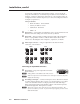
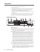
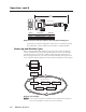
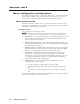
Table Of Contents
- Chapter One
- Introduction
- Chapter Two
- Installation
- Chapter Three
- Operation
- Front Panel Features
- Power-up and Default Cycle
- Window Select Buttons
- Input Selection
- Menus, Configuration, and Adjustments
- Picture Controls
- Auto Memories
- Memory Presets
- Additional Features
- Chapter Four
- Software Configuration and Control
- Chapter Five
- HTML Configuration and Control
- Accessing the Web Pages
- Viewing System Status
- Using the Configuration Page
- Using the File Management Page
- Using the Control Page
- Using the Background Page
- Chapter Six
- Special Applications
- Appendix A
- Specifications, Part Numbers, and Accessories
- Appendix B
- Firmware Update Guide
2-7
MGP 464 • Installation
PRELIMINARY
Pin RS-232 function Description
1 – No connection
2 Tx Transmit data
3 Rx Receive data
4 – No connection
5 Gnd Signal ground
6 – No connection
7 – No connection
8 – No connection
9 – No connection
Pin RS-422 function Description
1 – No connection
2 Tx- Transmit ground
3 Rx- Receive ground
4 – No connection
5 Gnd Signal ground
6 – No connection
7 Rx+ Receive data
8 Tx+ Transmit data
9 – No connection
N
The MGP 464 also has an RS-232-only Config port on a 2.5 mm TRS connector
on the front panel. For information on this port, see “Front Panel Features” in
chapter 3, “Operation.”
d
LAN connector — Plug an RJ-45 network cable into this
connector to connect the unit to a network (via a switch,
hub, or router) or to a single computer.
Activity LED — This yellow LED blinks to indicate
network activity.
Link LED — This green LED lights to indicate a good
network connection.
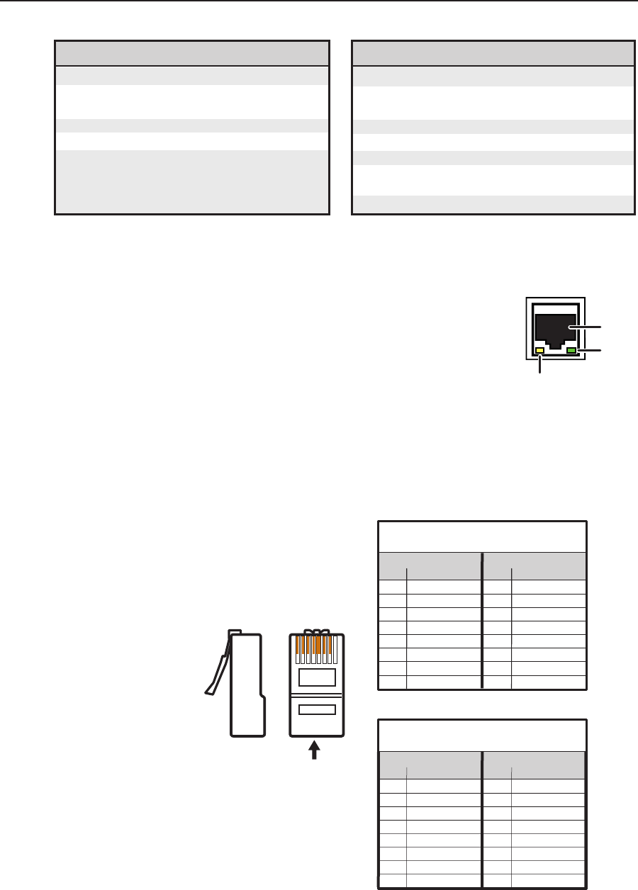
Use a straight-through cable to connect to a network, or a crossover cable to
connect directly to a computer.
• For 10BaseT (10 Mbps) networks, use a Cat 3 or better cable.
• For 100BaseT (max. 155 Mbps) networks, use a Cat 5 cable.
Straight-through Cable
(for connection to a switch, hub, or router)
End 1 End 2
Pin Wire Color Pin Wire Color
1 white-orange 1 white-orange
2 orange 2 orange
3 white-green 3 white-green
4 blue 4 blue
5 white-blue 5 white-blue
6 green 6 green
7 white-brown 7 white-brown
8 brown 8 brown
Crossover Cable
(for direct connection to a PC)
End 1 End 2
Pin Wire Color Pin Wire Color
1 white-orange 1 white-green
2 orange 2 green
3 white-green 3 white-orange
4 blue 4 blue
5 white-blue 5 white-blue
6 green 6 orange
7 white-brown 7 white-brown
8 brown 8 brown
RJ-45 connector
12345678
Insert
twisted
pair wires.
Pins:
Side View
LAN
RJ-45
Port
Link
LED
Activity
LED