User Guide MediaLink® MLC 60 Series MediaLink Controllers 68-2166-01 Rev.
Safety Instructions • English This symbol is intended to alert the user of important operating and maintenance (servicing) instructions in the literature provided with the equipment. This symbol is intended to alert the user of the presence of uninsulated dangerous voltage within the product’s enclosure that may present a risk of electric shock. Warning Power sources • This equipment should be operated only from the power source indicated on the product.
FCC Class A Notice This equipment has been tested and found to comply with the limits for a Class A digital device, pursuant to part 15 of the FCC Rules. Operation is subject to the following two conditions: 1. This device may not cause harmful interference. 2. This device must accept any interference received, including interference that may cause undesired operation.
Conventions Used in this Guide Notifications In this user guide, the following are used: CAUTION: NOTE: A caution indicates a potential hazard to equipment or data. A note draws attention to important information. TIP: A tip provides a suggestion to make working with the application easier. WARNING: A warning warns of things or actions that might cause injury, death, or other severe consequences.
Contents Introduction.......................................................... 1 About This Guide................................................. 1 About the MLC 60 Series MediaLink Controllers.. 1 MLC Models.................................................... 1 Features........................................................... 3 MLC Configuration Software........................... 5 Device Drivers.................................................. 5 Application Diagrams..................................
MLC 60 Series MediaLink Controllers • Contents vi
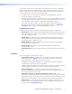
Introduction This section gives an overview of the guide and describes the MLC 60 Series MediaLink® Controllers and their features. Topics include: • About This Guide • About the MLC 60 Series MediaLink Controllers • System Requirements About This Guide This guide provides detailed information and best practice recommendations about cabling and configuring the Extron MLC 60 Series MediaLink Controllers.
MLC 62 RS MK — UK model. Controls devices by RS-232, IR, relays, and digital input; has a standard MK sized frame and fits into a standard one-gang MK electrical box. MLC 64 RS VC D — US model. Controls devices by RS-232, IR, relays, and digital input; has a two-gang Decora faceplate and fits in a two-gang US electrical box. Contains a volume control module with an analog potentiometer for volume control of an Extron amplifier.
The five MLC models have the same button functionality and use the same configuration software. All models can be controlled by pressing the front panel buttons or via a host device using RS‑232 communication and simple ASCII commands (Simple Instruction Set, SIS™). They differ from each other in the following ways: • The MLC 62 IR D rear panel does not contain the Relay, Digital Input, or RS-232 control ports that the RS models have.
• IR and RS-232 ports — The MLC 64 and the MLC 62 RS models each have a dedicated serial port for communicating with most types of projectors or flat panel displays via unidirectional RS-232. They also have an IR/S port, which can be configured for IR or RS-232 control. The MLC 62 IR D has only an IR port, which is used for IR communication only. IR and RS-232 display drivers can be downloaded and used to configure the controller.
MLC Configuration Software The included MLC Configuration Program is used to configure the MLC buttons and ports via an RS-232 or USB connection. This software, provided on a DVD that is delivered with the product, enables you to set functions for the front panel buttons and to configure the MLC ports in order to control devices via the MLC. The software works in combination with the IR or RS-232 drivers, also provided with the MLC on DVD or at www.extron.
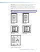
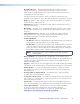
IR Projector Control Projector with Internal Speakers AY PL DIS F OF E ONLUM VO PC EO VGA VID Audio Video Audio Extron MLC 62 IR D MediaLink Controller • • • • PC IR Display Control On/Off Control Input Switching Volume Control DVD Figure 3. MLC 62 IR D Controlling a Projector PC Audio Audio DVD VGA RS-232 Display Control DI ON Audio Laptop Y LA SP Video VGA F OF ME LU VO Relay EO VID PC E T MU OP PT LA Extron SI 3 Surface-Mount Speakers Figure 4.
PC DVD Laptop Audio Video VGA Audio RS-232 Display Control Volume Control Audio Projector with Switched Audio Output VGA S-video ME LU VO AY PL DIS F OF ON PC OP PT Relay LA TE MU O E VID X AU Document Camera Extron MPA 152 Mini Power Amplifier UT TP 15 R ING 2 WIR ND SS GROU CLANOT RT TS! SHO TPU DO OR OU R AKE SPE R L TE MO RE E MUT VOL/ A 50m S UT INP ED LIST IDEO 17TTIO/VTUS AUDARA APP Screen Control 4/8 S OHM OU 2 MPA US C R 10V L Extron MLC 64 R
Features, Installation, and Operation This section describes the front, side, and rear panel features of the five MLC models, and provides procedures for installing and operating them.
4. Wire and connect the MLC power supply (see “Connecting Power to the MLC,” later in this section). Connect all other power cords and turn on all the devices, including the MLC. 5. Connect a configuration cable from the computer to the MLC by doing either of the following: • Connect a USB A to mini B cable to the MLC USB configuration port and to a USB port on your computer (see “Configuring the MLC via the USB Port,” later in this section).
The numbered callouts below apply to all the following MLC D front panel drawings.
Controls behind the wallplate The front panels of the MLC D controllers contain some controls and connectors that are located behind the wallplate when the controller is mounted. To access these features that are covered during normal operation, you must remove the wallplate (see “Accessing the Covered MLC D Front Panel Features,” later in this section).
Front panel features a Activity LED — This bicolored LED lights green when the MLC front panel buttons are pressed. It blinks red while enabling front panel lockout (executive mode). b Display power On and Off buttons — After configuring these buttons, use them to turn the connected display device or switcher on and off. The face of the On button contains a nub (j), which helps you to identify the button by touch. When the On button is pressed, it blinks rapidly while the connected device is warming up.
g USB configuration port — Connect a USB cable (USB A to mini B) between your computer and this port to configure the MLC via the configuration software and to update the firmware. This port can also provide power to the MLC during configuration. NOTE: h i Do not use this port as the permanent power source for the MLC. It should be used for power only during button and port configuration. • On the MLC D models, the USB port is located at the right edge of the front panel behind the wallplate.
Setting the button flashing rate — Specify fast or slow flashing of a front panel button and the number of seconds the button flashes. • NOTE: While a button is flashing, all other front panel buttons are disabled. • A user-defined RS-232 operation — Issue a non-driver-associated RS-232 command (one that you programmed separately), such as an SIS command, via the IR/S or the RS-232 port. • Button emulation — Initiate a series of button functions with a single button press.
a Host/Config port — This bidirectional RS-232 serial port can be used for configuration and firmware updates in the same way as the USB port (g in the “Front and Left Side Panels” section, earlier in this section). The baud rate is 9600 bps. This port can be used as a backup for the USB Configuration port (although you cannot power a device through it).
Rear Panel Features on MLC 62 RS EU and MLC 62 RS MK Only The items listed in this section are located on the rear panel of the MLC 62 RS EU and the MLC 62 RS MK only. On the MLC D models, these items are on the front panel, behind the wallplate (see “Rear Panel Features” for the descriptions of features a through f). 1 2 C RELAYS N/O Tx 1 0.4 A max PWR HOST/ CONFIG 2 8 12 V 9 Tx/ IR PORT B PORT A RS-232 IR/ S DIGITAL INPUT R + 1 Tx Rx 7 Figure 12.
Installation The MLC 60 Series can be installed as listed below: • The MLC 62 D models can be installed in a standard one-gang electrical wall box or a one-gang Decora mounting bracket (“mud ring”). • The MLC 64 RS VC D can be installed a two-gang electrical box or mounting bracket. • The MLC 62 RS EU can be installed in a standard one-gang EU junction box. • The MLC 62 RS MK can be installed in a standard one-gang MK junction box.
DISPLAY ON OFF VOLUME PC VIDEO Extron Figure 14. Removing the Faceplate (MLC 60 Series D Models) 2. If you are switching faceplates, transfer the buttons from the faceplate you removed to the replacement one. 3. Make any desired button changes (see “Replacing Buttons,” later in this section). 4.
Removing and replacing the MLC 64 VCM module knob and faceplate The MLC 64 is provided with one black and one white VCM faceplate and volume control knob. You can change the faceplate, knob, or both on the volume control module as described in the following procedures. Replacing the MLC 64 volume control knob NOTE: It is not necessary to remove the faceplate or the board from the wallplate in order to replace the knob. 1.
VOLUME MUTE Figure 17. Removing the MLC 64 Volume Control Module Faceplate 3. Making sure that both the faceplate and the volume control module board are upright, line up the pegs in the upper-left and lower-right corners of the new faceplate with the holes in the board. 4. Press the faceplate onto the board until the tabs at the top and bottom of the faceplate snap into their slots on the board.
2. If you are switching faceplates, transfer the buttons from the faceplate you removed to the replacement. 3. Make any desired button replacements (see “Replacing Buttons,” below). 4. Replace the faceplate as follows: a. Hold the MLC with its board against the back of the faceplate, aligning the two tabs on each side of the unit with the two slots on each side of the faceplate. DI ON SP LA Y Ridge on tab snaps into slot. LUOFF ME VO PC LA VID PT OP EO MU TE Slot Figure 19.
4. Press the two buttons into the faceplate until the pegs on the membrane are seated in the corresponding holes. 5. Repeat steps 2 through 4 for any additional buttons that you want to replace, then reattach the faceplate. Wiring for RS-232 Control (RS Models Only) The MLC 60 Series RS models can send out RS-232 commands through the Port A RS-232 port (Port A) or the IR/S port (Port B) to control a display device or switcher that is connected to the port.
Wiring for IR Control To control devices via infrared (IR) commands from the MLC, connect one or two IR emitters to the IR/S port (RS models) or the IR port (IR model). The IR and IR/S ports provide unidirectional IR signal output to control a display, projector, switcher, or other device such as a VCR or DVD player. You can connect one or two single IR emitters or one dual IR emitter to the IR or IR/S port to control one or two devices.
COMMON 2 1 GROUND Tx/IR GROUND HOST/ CONFIG DIGITAL INPUT 1 RELAYS N/O Tx GROUND Power Supply Pin: 3 2 1 Ground ( ) 110/220 V Ground ( ) Signal PORT B PWR RS-232 IR/ S 12V 0.2 A MAX GROUND Rx Low Voltage Screen Control MLC RS D Rear Panel Tx GROUND Motorized Screen Figure 25. Connecting a Motorized Screen to the Relay Port of an MLC RS D +12 VDC To connect devices to both relay ports: MLC 62 RS the D 1.
Example: The diagram below shows a two-position switch connected to the Digital Input port of an MLC 62 RS D. 1 COMMON DIGITAL INPUT Tx GROUND Pin: 2 1 Ground ( ) Digital Input 1 RELAYS N/O GROUND Rx HOST/ CONFIG Two-position Switch 2 1 GROUND IR/ S MLC RS D Rear Panel Tx/IR GROUND Tx GROUND PWR RS-232 12V 0.2 A MAX Figure 26.
Wiring the Volume Control Module (MLC 64 RS VC D Only) Connect the remote volume control port of an Extron amplifier to the 3-pole captive screw connector on the rear panel of the MLC 64 volume control module, as shown in the figure below. No software configuration is required for this module. NOTES: • Choose an Extron amplifier that is capable of remote volume control and muting. Not all Extron amplifiers have remote volume control ports. The MPA 122 or MPA 401 are examples of the type of amplifier to use.
1 COMMON HOST/ CONFIG DIGITAL INPUT Tx GROUND RELAYS N/O GROUND Rx GROUND Tx/IR GROUND Tx GROUND +12 VDC PORT A PWR RS-232 12V 0.4 A MAX 2 1 IR/ S 2. Plug the connector into the rear panel Pwr connector. In the example below, a power supply is being connected to the Pwr connector of an MLC 62 RS D. Ground 12 VDC Input MLC Rear Panel Ground All Devices External Power Supply (12 VDC) Figure 30.
Mini Type B USB Type A USB USB Cable USB 1 USB Ports MLC 62 RS EU or MLC 62 RS MK Left Side Panel PC Figure 32. USB Port Connection for MLC 62 RS EU and MLC 62 RS MK 3. If this is the first time you have connected an MLC to this USB port on your computer, the Found New Hardware Wizard opens. On the first screen, you can specify whether you want the computer to connect to Windows Update in order to search the web for the driver that it needs to communicate with the MLC via the USB port.
4. Click Next. On the next screen, make sure that the Install the software automatically (Recommended) radio button is selected, then click Next. (You do not need to insert a disc.) Figure 34. Selecting the Radio Button to Install the USB Driver Automatically Your computer locates the driver needed for it to communicate with the MLC via the USB port. This driver is loaded to the computer hard drive when the MLC configuration program is installed. 5.
IR Learning The IR learning transceiver sensor on the MLC front or left side panel can receive and “learn” commands from the infrared remote controls of other devices via the MLC configuration software. IR Learning enables you to create an IR driver file to control the projector or input devices such as a VCR or DVD player. IR Learning of projector control codes is necessary only if there is no driver available for your projector or if you need to customize the driver.
Mounting the MLC 60 Series Controllers When the system has been cabled, configured, and tested, the MLC can be installed in a wall or furniture. After you have any desired changes to the faceplate or front panel buttons and configured the buttons, mount the MLC as described in the following sections. Mounting an MLC 62 D You can mount an MLC 62 RS D or MLC 62 IR D to a UL-approved one-gang sized electrical junction box or Decora mounting bracket (included).
Mounting an MLC 62 D to a Decora Mounting Bracket A one-gang, Decora style mounting bracket (“mud rings”) is provided with the MLC 62 D models. If desired, you can mount the MLC to this type of bracket instead of to an electrical box. To mount the controller to a Decora style mounting bracket, follow these steps: 1. Cut a hole in the mounting surface large enough to accommodate the provided one-gang mounting bracket. 2. Insert the mounting bracket into the hole. 3.
Mounting the MLC 64 RS VC D Mounting an MLC 64 RS VC D to an electrical junction box CAUTION: Ensure that the junction box is grounded properly. 1. Mount a two-gang electrical junction box in the wall or furniture, following the directions provided with the box. 2. Run the cables through the electrical box. 3. Connect all cables and disconnect power from all devices at the source. 4. Place the MLC and VCM units side-by-side into the mounted electrical box. 5.
Mounting an MLC 64 RS VC D to a Decora Mounting Bracket A two-gang Decora mounting bracket is provided with the MLC 64. To mount the MLC 64 to this type of bracket: 1. Cut a hole in the mounting surface large enough to accommodate the provided two-gang mounting bracket. 2. Insert the mounting bracket into the hole. 3. Turn the two screws on the bracket so that the locking arms rotate behind the mounting surface until they clamp securely to it. Do not overtighten. 4.
Mounting the MLC 62 RS EU and the MLC 62 RS MK CAUTION: Ensure that the junction box is grounded properly. To mount the MLC 62 RS EU and MLC 62 RS MK to an electrical box: 1. Attach the provided metal mounting bracket to the mounted electrical box using two of the included screws in the slots at the top and bottom of the bracket.
Wall Wall Box Metal Bracket Y LA SP DI F OF E ONLUM VO EO VID PC Frame OP TE MU PT LA MLC 62 MK Figure 42. Mounting the MLC 62 RS MK to an External Electrical Box Mounting the MLC EU in a Raceway Using Spacers (Optional) If you are experiencing difficulty with the MLC EU staying in place when installed in a cable raceway, this may be due to a gap between the metal mounting bracket and the wall frame.
To mount the MLC EU to a raceway using the spacer: Raceway 1. Mount the electrical box in the raceway. 2. Attach the spacer to the electrical box using two of the included screws in the holes at the sides of the spacer. Leave the screw heads protruding approximately 1/8 inch from the surface of the spacer. Junction Box Mounting Bracket 3.
Accessing Covered Panel Features After Mounting After the MLC is installed in the mounting surface, you can still access the covered front panel features on the MLC D and the side and rear panel features on the MLC 62 RS EU and MLC 62 RS MK, using the following procedures. Accessing the Covered MLC D Front Panel Features After the MLC D is mounted, the following front panel items are covered by the wallplate: IR sensor, DIP switches, Reset button, and USB connector.
Y LA F OF E ONLUM Extron SP DI VO Insert to line. EO VID PC OP TE MU T AP L Figure 45. Inserting the Removal Tool in an MLC 62 EU 2. Press the removal tool inward or toward the mounting surface to release the tab holding the MLC in place in the wall frame. 3. If the MLC does not immediately come free of the frame, pry the unit outward (away from the wall) until it is free of the installation surface, then lift it out.
Resetting the MLC Using the Reset Button If it becomes necessary to reset the MLC to its default factory firmware or to the default configuration settings that were implemented at the factory, you can use either the Reset button (see below) or the configuration software (see the software help file). The Reset button is located on the front panel of the MLC D behind the wallplate, and on the rear panel of the MLC 62 RS EU and MK.
Software-based Configuration This section describes basic procedures for setting up the MLC using the MLC 60 Series Windows-based configuration program. The following topics are covered: • About the MLC Configuration Program • Installing the Configuration Software • Starting the Configuration Software • Obtaining Device Drivers For more detailed descriptions and additional configuration procedures, see the configuration program help file.
Installing the Configuration Software The software is provided on a DVD that is delivered with your MLC unit. You can also download it free of charge from the Extron website. Downloading and Installing the Software from the Web If you do not have the software on DVD, download it to your computer from the Extron website as follows: 1. Visit the Extron website at www.extron.com and select the Download tab. 2. On the Download Center screen, click the Control Software button.
3. On the Control Software screen, scroll to locate the MLC 60 Series, and click the Install link in the far right column. 4. Follow the on-screen instructions to complete the installation on your computer. Starting the Configuration Software To use the MLC to control devices, you must create one or more configurations for it, using the MLC configuration program.
5. Select your MLC model from the Select Model drop-down menu. Figure 49. Add Device Window with Select Model Menu Displayed 6. Click OK. The MLC 60 Series main window opens, with the device name you entered displayed in the device configuration tree (left column). Figure 50.
The MLC 60 Series main window is divided into the following major sections (see the illustration on the previous page): a The device configuration tree enables you to view the list of devices that have been configured, and to organize and save all these device configurations in a single project file. b The Front Panel tab screen enables you to configure the buttons and assign all commands to them.
Obtaining Device Drivers The Extron drivers are control files (libraries) of commands created by Extron that are specific to a particular display device or switcher. There are different sets of drivers for serial (RS-232) and IR control. Before you can use the configuration software to configure the MLC buttons and ports, the necessary drivers must be loaded onto your computer. You must then load the appropriate driver for your device to the MLC in order to configure it to control the device.
The Driver Subscriptions window opens. In the Available Drivers Subscription section, select the device types for which you want to download drivers. Figure 52. Driver Subscription Window • To select all device types available from a manufacturer, select the check box in front of the manufacturer name. Each manufacturer whose drivers you select is listed in the Current Drivers Selection column.
4. Click Download. The Driver Subscriptions Download window opens, displaying all drivers that have been selected or previously downloaded to your computer. Figure 53. Driver Subscription Download Screen • If a driver on the list is new for your computer, it has the designation “Waiting...” in the Status column. • If a driver already exists on your computer, its designation is “Already in Driver Catalog.” NOTE: Your computer must have an active internet connection to download the drivers. 5.
Downloading Drivers from the Disc The software DVD provided with the MLC contains the set of device drivers that are also available from the web. To load the drivers from the DVD to your computer: 1. Load the Extron Software Products DVD into your CD or DVD drive. The disc should start automatically. If it does not, open your Windows Explorer and double-click Launch.exe on the CD or DVD drive to start it. 2. On the opening screen, click the Drivers button or select the Drivers tab at the top of the screen.
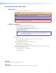
The MLC 60 Series Device Drivers screen opens, displaying a list of all available drivers for use with the MLC 60 Series controllers (see the example below). Figure 57. MLC 60 Device Drivers Page on DVD 4. From the DVD, you can download either the current Extron driver package (containing all IR and serial drivers that were available at the time the package was compiled), or an individual driver.
NOTE: The DVD may contain additional drivers that became available after the current driver package was created. These new drivers may be on the DVD, but have not been incorporated into the driver package. To ensure that you are getting all the drivers currently available, use the configuration program to download the drivers (see “Downloading the Drivers Using the Configuration Program,” earlier in this section). To download a single driver: a.
Downloading Drivers from the Web Drivers can also be obtained directly from the Extron website as follows: 1. Visit the Extron website at www.extron.com, and click the Download tab. 2. Click the Device Drivers link on the left panel of the Download Center screen. 3. From the drop-down menu on the Device Drivers screen, select MLC 60 Series. Figure 59. Selecting MLC 60 Series from the Device Drivers Drop-down Menu 4.
As you make each selection, the driver list below changes to display all available drivers meeting your selected criteria. Figure 60. Entering MLC 60 Series Driver Search Criteria 5. Click on the device name whose driver you want to download. To download all the drivers in the current package, click the Download install for driver package (Version n) link. NOTE: The website may contain additional drivers that became available after the current driver package was created.
SIS Control The MLC can be remotely controlled via a host computer or other control device that is attached to the MLC rear panel Host/Config port. You can issue Simple Instruction Set (SIS) commands to the MLC via the RS-232 or USB interface of your computer or control device with a communication software program such as Extron DataViewer or HyperTerminal. This section contains a list of the SIS commands available for the MLC and describes procedures for issuing them.
Using the Command and Response Table The Command and Response Table on the following pages lists valid ASCII command codes, the responses of the MLC to the host, and a description of the command function or the results of executing the command. The ASCII to HEX conversion table below is for use with the table.
X1@ = Name of the MLC device. May be up to 24 alphanumeric characters. The first character must be alphabetic; the last character cannot be a hyphen or minus sign (-). No blank or space characters are permitted. X2# = Status 0 = disengaged (default) 1 = engaged X2% = Firmware compatibility version number (a 3-digit number listed to three decimal places: nnn.nnn) X2^ = Device configuration compatibility version number (a 3-digit number listed to three decimal places: nnn.
On the MLC 64, the LEDs are numbered as follows: LED Number LED Location 1 Transmit red 2 Transmit green 3, 4, 5, 6 Four LEDs behind “Display” text 7 Button row 1, first LED (button 1) 8 Button row 1, second LED (button 2) 9, 10, 11 Button row 2, LEDs 1 through 3 12, 13, 14 Button row 3, LEDs 1 through 3 15, 16, 17 Button row 4, LEDs 1 through 3 18, 19, 20 Button row 5, LEDs 1 through 3 21 through 32 Not used (The status is always 0.
Command and Response Table for SIS Commands Command ASCII Command Response E B* X! BTNO} BtnoB* X! ] (Host to Unit) (Unit to Host) Additional Description Button Selection Trigger a button Execute the commands programmed to button X!. (This command produces the same results as pressing button X! on the front panel). X! = 01, 02, 03, 04, 05, 06, 07, 08, 09, or 10.
Command ASCII Command (Host to Unit) Response (Unit to Host) Additional Description Relay Functions (RS models only) X@*3*X# O Rly X@*X2# ] 2*3*1O Rly2*1 ] Toggle relay X@*2 O Rly X@*X2# ] Force relay on X@*1 O Rly X@*1 ] Force relay off X@*0 O Rly X@*0 ] View relay state X@ O X2# ] Pulse relay Example: Set the length X# of the pulse specified for relay port X@. Values for X# represent increments of 0.5 seconds and can range from 1 (0.5 seconds) to 255 (approximately 130 seconds).
Command ASCII Command Response E ZXXX } ZapXXX ] Reset the MLC configuration to the factory default. Q X* ] Q 1.00 ] **Q X2% ] E DIMQ } X2^ ] Display firmware version X* to two decimal places. The current firmware version is 1.00. Display firmware compatibility version X2%. View the device configuration compatibility version number X2^.
Command ASCII Command Response E LC } X5) ] (Host to Unit) Additional Description (Unit to Host) Query LED status View LED status On MLC 62 models, the LEDs are numbered as follows: 1 =Transmit red 2 = Transmit green 3-6 = Display text LEDs 1 through 4 7 = Button row 1, first LED 7 8 = Button row 1, second LED 9-12 = Volume text LEDs 1 through 4 13 – 17 13-17 = Volume LEDs 1 through 5 18 18 = Button row 2, first LED 19 = Button row 2, second LED 20 20 = Button row 3, first LED 21 = Button row 3, se
Reference Information This section contains the specifications for all models of the MLC and lists names and part numbers of included parts and optional accessories for the product.
Control — digital input monitoring port (RS models) Number/type ���������������������������������� Connector �������������������������������������� Digital inputs Input voltage range ����������������� Input impedance ���������������������� Programmable pullup ��������������� Threshold low to high �������������� Threshold high to low �������������� 1 digital input (configurable) (1) 3.5 mm captive screw connector, 2 pole 0-24 VDC 12k ohms 2k ohms to +5 VDC >1.5 VDC <1.
MLC 62 RS EU MLC 62 RS EU Faceplate ��������������������������� Fits the opening in a 1-gang EU, fits a Jung AS 500 wallplate or other European frame that accepts 55 mm x 55 mm modules. Wall frame ������������������������� 3.2" H x 3.2" W x 0.4" D 8.1 cm H x 8.1 cm W x1.0 cm D Device �������������������������������� 2.2" H x 2.2" W x 1.5" D (5.5 cm H x 5.5 cm W x 3.7 cm D) Depth includes connectors and buttons. Allow enough depth in the junction box for device plus cable clearance.) 2.79” (7.08 cm) 0.
Product weight MLC 62 IR D, MLC 62 RS D ������ MLC 62 RS EU ������������������������� MK models ������������������������������ Shipping weight ����������������������������� Vibration ���������������������������������������� Regulatory compliance Safety �������������������������������������� EMI/EMC ��������������������������������� Accessibility ����������������������������� MTBF ��������������������������������������������� Warranty ���������������������������������������� 1.0 lb (0.5 kg) 1.0 lb (0.
MLC 64 RS VC D Specifications Control — host ports Serial control port ��������������������������� Baud rate and protocol ������������������� Serial control pin configuration ������� USB control port ����������������������������� USB standards �������������������������������� IR learning frequencies ������������������� IR learning distance ������������������������ Program control ����������������������������� 1 bidirectional RS-232 on a 3.
General Power supply MLC 64 RS D ��������������������������� External Input: 100-240 VAC, 50-60 Hz Output: 12 VDC, 1 A, 12.0 watts Remote volume control ������������ 10 VDC, supplied by the Extron device being controlled Power input requirements MLC 64 RS D ��������������������������� 12 VDC, 0.4 A, max. Remote volume control ������������ Unmute mode: 0.2 watts, 18 mA, 10 VDC Mute mode: 0.
MTBF ��������������������������������������������� 30,000 hours Warranty ���������������������������������������� 3 years parts and labor NOTES: • All nominal levels are at ±10%. • Specifications are subject to change without notice.
Part Numbers and Accessories Included Parts These items are included with the MLC 60 Series controllers: MLC 62 RS D Included Parts Replacement Part Number MLC 62 RS D MediaLink Controller 60-1005-02 12 VDC, 1 A external power supply (PS 1210C) 70-775-01 Front faceplates, eight-button, 1 black and 1 white (Include additional buttons with assorted labels) 70-688-12 Decora wallplate, 1-gang, black Decora wallplate, 1-gang, white Extron Tweeker (slotted Phillips #1 screwdriver) MLC 60 Series Setup Gui
MLC 62 RS EU Included Parts Replacement Part Number MLC 62 RS EU MediaLink Controller (RAL9010 white) 60-1005-35 12 VDC, 1 A external power supply (PS 1210C) 70-775-01 Front faceplate, 6 button (RAL9010 white) Front faceplate, 8 button (RAL9010 white) Jung AS500 wall frame (RAL9010 white) Extron Tweeker (slotted Philips #1 screwdriver) MLC 60 Series Setup Guide (2) 3.5 mm 3-pole captive screw connectors (4) 3.
MLC 64 RS VC D Included Parts Replacement Part Number MLC 64 RS VC D MediaLink Controller 60-1182-02 12 VDC, 1 A external power supply (PS 1210C) 70-775-01 MLC 64 Front faceplate, black, six-button (Includes additional buttons with assorted labels) MLC 64 Front faceplate, white, six-button (Includes additional buttons with assorted labels) VCM front faceplates, 1 black and 1 white Volume control knobs, 1 black and 1 white Decora wallplates, 2-gang, 1 black and 1 white Extron Tweeker (slotted Philips #
Accessories These optional items can be ordered separately: Accessories Part Number For Model English button kit (MLC 62 RS EU and MLC 62 RS MK models) 70-728-01 MLC 62 RS EU, MLC 62 RS MK French and German button kit (MLC 62 RS EU and MLC 62 RS MK models) 70-728-11 MLC 62 RS EU, MLC 62 RS MK MLA VC10 Plus Volume Control Module (MLC 62 models) 60-1090-01 All MLC 62 MPA 152 Stereo Power Amplifier, 15 watts per channel MPA 152 ENERGY STAR® Qualified Stereo Power Amplifier 60-844-01 60-844-02 All
Extron Warranty Extron Electronics warrants this product against defects in materials and workmanship for a period of three years from the date of purchase.