User’s Manual CTP150CM www.extron.com Extron Electronics, USA Extron Electronics, Europe Extron Electronics, Asia Extron Electronics, Japan 1230 South Lewis Street Anaheim, CA 92805 USA 714.491.1500 Fax 714.491.1517 Beeldschermweg 6C 3821 AH Amersfoort The Netherlands +31.33.453.4040 Fax +31.33.453.4050 135 Joo Seng Road, #04-01 PM Industrial Building Singapore 368363 +65.6383.4400 Fax +65.6383.4664 Daisan DMJ Building 6F 3-9-1 Kudan Minami Chiyoda-ku, Tokyo 102-0074 Japan +81.3.3511.7655 Fax +81.
Precautions Safety Instructions • English This symbol is intended to alert the user of important operating and maintenance (servicing) instructions in the literature provided with the equipment. This symbol is intended to alert the user of the presence of uninsulated dangerous voltage within the product's enclosure that may present a risk of electric shock. Caution Read Instructions • Read and understand all safety and operating instructions before using the equipment.
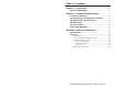
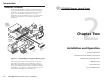
Table of Contents Chapter 1 • Introduction .......................................................... 1-1 About the CTP150CM ........................................................... 1-2 Chapter 2 • Installation and Operation .......................... 2-1 Installation Overview ......................................................... 2-2 UL Requirements for Wall Box Installation .............. 2-3 Wall Mounting Site Preparation .................................... 2-3 Wall Mounting .....................
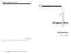
Table of Contents, cont’d CTP150CM Remote Control Panel 1 Chapter One Introduction About the CTP150CM 68-994-01 Rev. A Printed in the USA 05 04 All trademarks mentioned in this manual are the properties of their respective owners.
Introduction, cont’d Introduction About the CTP150CM The Extron CTP150CM is a 7-button contact closure remote control panel that can be connected to the TPT150 switching transmitter of a TPS150 switching and transmission system (figure 1-1). Each button corresponds to one of the transmitter’s front panel functions and you can operate these functions from the remote control panel or the TPT150 transmitter. Extron TPR150 Control System Twisted Pair Receiver 3Hz A; 47-6 0.
Installation and Operation, cont’d Installation and Operation Installation Overview CAUTION Installation and service must be performed by authorized personnel only. UL Listed electrical boxes are recommended. See UL Requirements for Wall Box Installation in this chapter. 1 Power off all devices and disconnect them from the power source, if necessary. 2 Run an 8-conductor cable between the site where the CTP150CP control panel module will be installed and the site of the TPT150 transmitter.
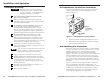
Installation and Operation, cont’d Installation using a UL listed wall box (available from Extron) is recommended for most mounting options, but the optional wall mounting bracket can be used instead. All wall boxes must be at least 1.0" (2.5 cm) deep. Before using the wall mounting bracket, verify that the installation conforms to national and local electrical codes. Prepare the site as follows: 1.
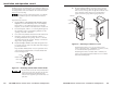
Installation and Operation, cont’d 6. If you are using a mounting bracket, follow the directions, if any, that came with the mounting bracket to attach the clips that fasten the bracket to the wall or furniture (figure 2-4). 2. If not already accomplished, attach the 8-conductor cable to the rear of the remote control panel. 3. Mount the CPM101 or other mini-AAP panel (with the attached remote control panel) to the wall box or mounting bracket using the two included mounting screws (figure 2-5).
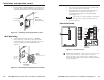
Installation and Operation, cont’d Front Panel Operation The control panel (figure 2-7) emulates many front panel controls of the TPT150 transmitter. See the TPS150 manual for more details for each control. PC 1 PROJECTOR POWER 2 1 PC 2 1 VIDEO 1 VOLUME UP VIDEO 2 DOWN 3 1 3 1 Figure 2-7 — Front panel 1 Input select buttons — The PC 1, PC 2, Video 1, and Video 2 buttons select video and audio inputs 1 through 4 on the TPT150 transmitter.
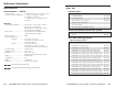
Reference Information, cont’d Reference Information Specifications Control/remote — TPS150 Contact closure ............................ (1) 3.
Reference Information, cont’d Architectural solutions Description RGB 468 Mxi (black) Part number 60-591-02 RGB 468 Mxi (white) 60-591-03 CIA111 (black, with cable guards) 60-596-12 CIA111 (white, with cable guards) 60-596-13 CIA111 (black, without cable guards) 60-596-22 CIA111 (white, without cable guards) 60-596-23 RGB 478 Mxi (black) 60-592-02 RGB 478 Mxi (white) 60-592-03 Table solutions Description CPM208-1 Mini-AAP bay Part number 60-589-13 CPM212-1 Tabletop mini-AAP bay (black)