User Guide IP Link® IPL T PCS4 IPL T PCS4i IP Link Power Control Interfaces 68-738-07 Rev.
Safety Instructions • English This symbol is intended to alert the user of important operating and maintenance (servicing) instructions in the literature provided with the equipment. This symbol is intended to alert the user of the presence of uninsulated dangerous voltage within the product’s enclosure that may present a risk of electric shock. Warning Power sources • This equipment should be operated only from the power source indicated on the product.
FCC Class A Notice This equipment has been tested and found to comply with the limits for a Class A digital device, pursuant to part 15 of the FCC Rules. Operation is subject to the following two conditions: 1. This device may not cause harmful interference. 2. This device must accept any interference received, including interference that may cause undesired operation.
Conventions Used in this Guide Notifications In this user guide, the following are used: WARNING: CAUTION: NOTE: A warning warns of things or actions that might cause injury, death, or other severe consequences. A caution indicates a potential hazard to equipment or data. A note draws attention to important information. TIP: A tip provides a suggestion to make working with the application easier.
Contents Introduction............................................................ 1 About this Guide................................................. 1 About the IPL T PCS4........................................... 1 Features............................................................... 1 Application Diagrams........................................... 2 Installation and Rear Panels................................ 4 Installation Overview............................................ 4 Rear Panels..........
IPL T PCS4 • Contents vi
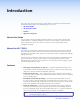
Introduction This section gives an overview of the IPL T PCS4 and IPL T PCS4i Power Control Interfaces and describes their features. The following topics are covered: • About this Guide • About the IPL T PCS4 • Features • Application Diagrams About this Guide This user guide contains information about the Extron IPL T PCS4 and IPL T PCS4i Power Control Interfaces, including explanations of how to install, configure, and operate them.
• Grouping of receptacles — To support dual powered devices by controlling them simultaneously, two or more receptacles can be grouped together. Grouping and ungrouping can be done via the front panel, TCP ports using Simple Instruction Set (SIS™) commands, or the internal web pages. • Detection device (alarm relay) — This relay on the rear panel can be connected to a relay-controllable siren or other detection device, and can be programmed to react at specified power level thresholds.
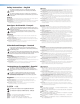
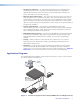
TCP/IP Network N LA 4 M AR AL 3 Alarm 2 AX AM 1 AD 10 L LO TA TO 0V 0-24 10A 0V -24 200 Extron IPL T PCS4i 60 50/ 20 Hz Codec Power Control with Sensing Capabilities Camera Monitor Projector Figure 2.
Installation and Rear Panels This section contains installation and cabling instructions for the PCS4. The following topics are discussed: • Installation Overview • Rear Panels • Setting Up the LAN Port • Connecting the Devices Installation Overview To install and set up an IPL T PCS4 interface, follow these steps: 1. Turn off all of the equipment.
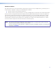
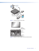
Rear Panels 100-120V 10A 1 2 3 4 S/N XXXXXXXXX E0000 0408 5 00-05-A6-XX-XX-XX ALARM 100-120V 50/60 Hz 1 LAN TOTAL LOAD 10A MAX 3 2 4 Figure 4. IPL T PCS4 Rear Panel (120 VAC) 200-240V 10A 1 2 3 4 S/N XXXXXXXXX E0000 0408 5 00-05-A6-XX-XX-XX LAN ALARM 200-240V 50/60 Hz 1 TOTAL LOAD 10A MAX 3 2 4 Figure 5. IPL T PCS4i Rear Panel (220 VAC) a Power connector — Connect a power cord from the AC power supply to this male IEC power input receptacle.
Setting Up the LAN Port LAN Port Cabling • For 10Base-T (10 Mbps) networks, use a Category 3 or better cable. • For 100Base-T networks, use a Category 5 cable. • Use a straight-through cable to connect to a switch, hub, or router. • Use a crossover cable to connect directly to a PC. Wire the connector as shown in the tables below.
3. Plug the power cord of each device to be monitored into one of the receptacles on the back panel of the PCS4. 4. If desired, connect a relay-controllable siren or other detection device to the Alarm relay on the rear panel. NOTE: The alarm relay cannot be set up from the front panel. You must use either SIS commands or the web pages to configure it (see the Power receptacle Monitoring and Alarm Functions SIS commands in the “SIS Programming and Control” section).
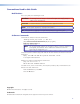
Front Panel Features and Operation This section contains a description of the IPL T PCS4 and IPL T PCS4i front panel features and instructions for setting up the PCS4 using the front panel. The following topics are discussed: • Front Panel Features • Setting Up the System Using the Front Panel • Resetting the Unit Front Panel Features 6 7 IPL T PCS4 1 R 2 7 1 7 6 2 6 6 7 4 3 F F F F S S S S SET REFERENCE FULL STANDBY 100 LINK ACT 5 4 3 Figure 7.
e LAN status LEDs — These three LEDs show the status of the Ethernet connection as follows: • 100 — When lit, indicates a 100 Mbps connection speed. Otherwise, the connection speed is 10 Mbps. • Link — Indicates that the interface has an active network connection. Act — (Activity) Blinks while data is being sent or received. Power LEDs (red) — (One for each receptacle) Indicate that power is being supplied to the attached device.
There are two common types of power for electronic devices: soft and hard. • Soft power devices normally have three power states: On, Standby, and Off. Such devices include projectors, DVD players, and VCRs. Example: On soft power devices, the Standby mode allows the unit to be powered to its Full power mode via RS-232 commands or a remote. Pressing a PCS4 receptacle button to Off when the receptacle is connected to a device that supports Standby power causes the device to power off.
Setting the Standby power threshold SET REFERENCE FULL STANDBY 1. Power off the attached device. 2. Press and hold the Standby button (shown at right). 3. While holding down the Standby button, press and release the receptacle button for the same device for which you set the Full threshold. The Standby LED for the selected receptacle blinks twice and remains lit. 1 Standby LED F S Receptacle Button 4. Release the Standby button. 5.
Clearing thresholds To remove the reference threshold settings from any receptacle: 1. Shut off power to the receptacle that you want to clear by pressing its button on the front panel. The red LED to the right of the button shuts off. 2. Press and hold the Standby or Full button while pressing and releasing the receptacle button. All three receptacle LEDs flash twice, indicating that the settings have been cleared. 3. Release the Standby or Full button that you were holding.
Resetting the Unit There are four ways to reset the PCS4 unit (called modes 1, 3, 4, and 5 for the sake of comparison with other Extron IPL products). Reset the unit by pressing the Reset button on the front panel (see “Front Panel Features” for the button location). This button is recessed; it can be accessed with a pointed stylus, ballpoint pen, or small Phillips screwdriver. CAUTION: IPL T The reset modes described on the following pages break all TCP/IP connections by closing all sockets to the unit.
Mode 3 Activation Hold the Reset button in until the Power LED blinks once (approximately 3 seconds). Release it, then immediately press it again momentarily (for less than 1 second). NOTE: Nothing happens if the momentary press does not occur within 1 second. Result Turns events on or off, depending on their current state. During resetting, the reset LED flashes two times if events are starting and three times if events are stopping. Purpose and notes This mode is used for troubleshooting.
HTML Configuration and Control The IPL T PCS4 must be configured before use, or it cannot control other devices. In addition to using the buttons on the PCS4 front panel, you can configure and control the PCS4 via any computer attached to a LAN by using the embedded web pages or SIS commands. This section describes the web pages and provides instructions for using them to configure the IPL T PCS4 series interfaces.
3. If the PCS4 has never been configured and is still set for factory defaults, skip to step 4. If not, perform a mode 4 system reset to restore the factory-set values (see “Resetting the Unit” in the “Front Panel Features and Operations” section for the resetting procedure). NOTE: The PCS4 must be configured with the factory default IP address (192.168.254.254) before you execute the ARP command, as described below. 4.
The response should be the new IP address of the PCS4, as shown below. Figure 10. Screen Showing the Ping Command You can reconnect using either Telnet or a web browser to verify that the update was successful. 6. After verifying that the IP address change was successful, issue the arp -d command at the DOS prompt to remove the address from the ARP table. For example: arp -d 10.13.170.15 A space must separate arp from the hyphen (-).
Setting up the computer for IP communication Follow these steps to set up communication between your computer and the PCS4. NOTE: The procedure and illustrations in this section are for Windows XP. For other Windows versions, the screens may appear slightly different. 1. Open the Network Connections page as follows: a. From the Start menu, select My Network Places. b. From the Network Tasks left side-bar menu, select View Network connections. 2.
4. Write down your the current IP address of your computer and its subnet mask below. You will need to restore these settings to the computer later. If an IP address automatically has been selected, make a note of that. If not, write down the following: IP address: __________________________ Subnet mask: __________________________ 5. Change the IP address of the computer temporarily so that it can communicate with the PCS4. a. Select the “Use the following IP address:” radio button. b.
7. Set up the PCS4 IP address (see “Configuring the IPL T PCS4 using a web browser,” later in this section, for the procedure). After the PCS4 has been reconfigured, an Ethernet (intranet or Internet) connection can subsequently be used to configure or control it. NOTE: Both your computer and the PCS4 must be connected to the same LAN. Alternatively, you may use a crossover Ethernet cable to connect the interface directly to your computer Ethernet card. 8.
4. IP, gateway, and subnet mask addresses follow standard naming and numbering conventions and protocol (nnn.nnn.nnn.nnn). The IP network administrator should provide the addresses to be used with this interface. Enter the new IP address assigned for the PCS4, the corresponding subnet mask, and gateway address, then click Submit. The PCS4 takes approximately 2 minutes to store the new settings.
Viewing the System Status The System Status web page, accessed by clicking the Status tab, provides information on the current settings. Changes must be made via the Configuration web pages or SIS commands (see the “SIS Programming and Control” section). Personnel who have user access can view this page but cannot access the Configuration or File Management pages to make changes. The following figure shows an IPL T PCS4 System Status web page. Figure 13.
Configuration There are seven Configuration web pages, which only administrators can access. They are listed in the side-bar menu at the left of the Configuration screen. The following sections discuss the tasks that you can perform on these screens. Specifying system settings On the System Settings screen, you can set the date and time, and change the IP address information for the PCS4. To change the available system settings: Figure 14. System Settings Screen on the Configuration Tab 1.
• Subnet mask: The subnet mask is used to split IP networks into a series of subgroups (subnets). The mask is a binary pattern that is matched up with the IP address to turn part of the host ID address field into a field for subnets. You can enter a new subnet mask address using the same format that is used for the IP Address. Date and time settings The following settings are available in the Date/Time Settings section. NOTE: This section lets you set the date and time on your PCS4 unit.
Assigning passwords The Passwords screen allows you to assign passwords to the administrator and user access levels. The administrator password gives access to all IPL T PCS4 web pages, enabling the administrator to configure the PCS4. The user password provides access only to the System Status web page. If you are logged in as user, you see only the Status tab with the System Status screen. You cannot make any configuration changes. To assign passwords: 1.
Entering e-mail addresses for alerts If you have created scheduled events or monitoring tasks on the PCS4, you can write an e-mail alert with a message corresponding to that event or task (for example, a change in power level for one of the attached devices). The e-mail alert can notify up to 48 recipients at one time; the Email Alerts screen lets you enter up to 48 e-mail addresses. Figure 16. E-mail Alerts Screen (Upper Portion) To edit notification e-mail addresses: 1.
8. Click the Save button beside the file name that you entered. The e-mail alert information is saved on the PCS4, and the Save button becomes Edit again. 9. Repeat steps 5 through 8 for each e-mail recipient address that you want to add or edit. Upgrading firmware The Firmware Upgrade screen lets you browse to locate and upload a new version of firmware for your unit. The uploaded file must have the file extension .S19. NOTE: The PCS4 .S19 file is not the same as the .
Figure 18. Switching/Grouping Screen Switching power to receptacles on and off To turn power to receptacles on and off: 1. On the Configuration tab, select Switching/Grouping from the side-bar menu. 2. In the Power column, select the On or Off radio button beside the number of each receptacle that you want to switch. If you want to switch a group of receptacles, select On or Off for one of the receptacles in that group (see Grouping receptacles, below). 3. Click Submit to put your changes into effect.
Monitoring the receptacles and setting the alarm The Monitor screen on the Configuration tab lets you monitor each receptacle for any change in its power or its reference threshold condition (full or standby power). You can also configure the alarm relay and set up the alarm to sound, send an e-mail notification, or both if any condition at a receptacle changes. This screen is updated continually. In addition, you can update it by clicking Refresh.
• Activate Relay: Select this check box to specify that the relay alarm will sound (activate) if the selected condition is met. If this box is not selected, any changes you make to the alarm relay settings are ignored. • Alarm status: Indicates whether or not the PCS4 has detected the condition that is being monitored. This column can display the following: • Inactive — Appears when the receptacle is not being monitored, or the condition being monitored has not been detected.
Scheduling power to receptacles The Schedule screen on the Configuration tab lets you schedule when power to the receptacles is turned on and off. You can schedule receptacles individually to turn on or off at desired times, or you can select a group of receptacles to turn on or off at one time. Clicking the Clear Schedule button deletes all schedules. You may want to set up your schedule for a week at a time, or a day at a time.
Scheduling receptacles by day of the week There are two types of schedules that you can set up for one day of the week. The two setup procedures are described below. All receptacles on and off: Follow this procedure to select both the powering on and powering off times for all desired receptacles on one day of the week. 1. Click on a day of the week at the top of a column in the scheduling table. Two Set Schedule For sections open, one for Power On and one for Power Off.
One receptacle, power on or off: Follow this procedure if you want to schedule only powering on or powering off of only one receptacle on one day. 1. In the scheduling table, click on the time displayed or the - symbol in the cell beside On or Off for the receptacle number that you want to set, in the column for the day you want to schedule. A Set Schedule For section appears. In the following illustration, the red box indicates the cell that was selected: receptacle 2, powering off, on Tuesday. Figure 22.
Uploading files to the web page The IPL T PCS4 has approximately 900 kbytes of space for user files to be uploaded. The Bytes Left field shows how much space remains for uploading files. To upload files: 1. Select the File Management tab on the IPL T PCS4 web page. 2. On the File Management screen, click Browse to open a Windows file selection window. 3. On the file selection window, locate and select a file to upload. (Only one file at a time can be selected.
Custom Web Pages On the PCS4, custom web pages are supported. You can determine the layout and appearance of the pages displayed on your screen. Server side includes (SSIs) enable you to obtain information from the unit and display the information on web pages. Query strings allow you to send information and commands to the unit to change its configuration or provide you with feedback. (See “Query Strings,” on the next page.
The query string in the figure below turns off DHCP on the IP Link device. URL with a Query String Using an SIS Command SIS Command Receptacle on Tells web server that SIS command follows. SIS Command To Be Processed by the IP Link HTML Code for a Link Linked Text Closes link. *Enter with no spaces. Figure 25.
Notice, in the figure below, that the commands executed by the PCS4 in response to SSI references have been replied to, and were implemented when the web page was served to the browser. Figure 28. Browser View of Previous HTML Source Code URL Encoding URL (Universal Resource Locator) encoding is a method of using ASCII hexadecimal characters to display specific characters in a URL. It is used for several reasons.
Reserved characters Reserved characters should not be encoded when they appear in their conventional meaning in a URL. For example, do not encode the slash (/) when using it as part of the URL syntax. Only encode unsafe characters (defined in the table in the next section) in your URLs. The following table lists reserved characters.
A/V Device Power Control Power control of A/V devices may be accomplished once the PCS4 interface has been connected and configured. These include web pages and Telnet. Custom Web Pages These pages can either be modified versions of the existing web pages, or new web pages developed in the field. Web page development can be done with a web site development tool such as FrontPage or Dreamweaver.
3. At the prompt, enter the IP address of the PCS4 unit. (The default IP address is 192.168.254.254. If the address was changed in the setup or configuration process, use the new address.) Telnet defaults to port 23. Figure 33. Connecting to the IP Address 4. If passwords were set up for the connected system, you are prompted to log in as an administrator or a user. Otherwise, the system responds with a carriage return and line feed (). 5.
Network Connections 1. Check the network connections and make adjustments as needed. The Link LED is solid green if a network connection is detected. The yellow ACT LED blinks if there is activity on the network. If these LEDs are not lit, either the cable is faulty or not plugged in, or the wrong type of cable is being used (see “Connecting the Devices” in the “Installation and Rear Panel” section). 2.
Downloading Global Configurator Software The Global Configurator (GC) software is an alternative to using the web pages to configure and monitor the PCS4. GC is a free asset management software that enables flexible, centralized, web-based power management for A/V systems. Using Global Configurator software, administrators can view the immediate status and power levels of all connected devices, schedule powering on and off of the devices, and configure the alarm triggers.
SIS Programming and Control This section provides instructions on using the Extron Simple Instruction Set (SIS) commands, which you can use to set up and control the IPL T PCS4 from a host computer or other control system attached to the rear panel LAN port.
Password Information The ] Password: prompt is displayed only if there is a password defined in the unit. It requires a password (administrator level or user level) followed by a carriage return. The prompt is repeated if the correct password is not entered. If the correct password is entered, the unit responds with ] Login Administrator ] or ] Login User ], depending on the password entered. If the passwords are the same for both administrator and user, the unit defaults to administrator privileges.
Using the Command and Response Table The PCS4 can be controlled via either a Telnet connection (port 23) or a web browser connection (port 80). The ASCII commands listed in the tables perform the same functions, but they are encoded differently to meet the requirements of each port (Telnet or browser). The ASCII to hexadecimal (HEX) conversion table below is for use with the command and response tables. Space ASCII to Hex Conversion Table • Figure 36.
Symbol Definitions ] = CR/LF (carriage return + line feed) (hex 0D 0A) } = Soft carriage return (no line feed, hex 0D) (For web browser commands, use the | [pipe] character instead of the soft return.) | = Pipe (vertical bar) character • = Space 24 = The 24 superscript indicates commands that give an E24 (privilege violation) message if you are not logged in at the administrator level. E = Escape key (hex 1B) (For web browsers, use W instead of E.
X3$ = Daylight saving time (DST) is a 1-hour offset to reflect the time during which clocks are set one hour or more ahead of local standard time, to provide more daylight at the end of the working day. Supported for the U. S. and parts of Brazil and Europe. Example: Time in California is GMT -8:00 from March to November and GMT -7:00 from November to March.
X70^ = Clear value 0 = condition no longer met 1 = clear with output off 2 = clear with output on 3 = clear with no threshold 4 = clear with standby threshold 5 = clear with full threshold 6 = clear with any change 7 = manual X70& = Relay polarity 0 = normally open 1 = normally closed X70* = Time to hold alarm active before canceling 0 = never times out 1-7 = 1 to 7 minutes X70( = On timed value 00-15 (in 250 ms increments) X71) = Off timed value 00-15 (in 250 ms increments) X71! = Day of t
Command and Response Table for SIS Commands Command ASCII (Telnet) (Host to Switcher) URL Encoded (Web) (Host to Switcher) Response (Switcher to Host) W X! %2A 1PC| W X! %2A 0PC| W X! PC| W X! PS| W X1)1 X1)2 X1)3 X1)4 GP| W 0000GP| W GP| W X1^ DT| Cpn X!•Ppc1] Cpn X!•Ppc0] X% ] X( ] Pgp X1)1 X1)2 X1)3 X1)4 ] Pgp0000] X1)1 X1)2 X1)3 X1)4 ] Pdt X1^ ] X1^ ] Ptf X! ] Pts X! ] Power Receptacle Control / Current Sense View power up delay Set individual full threshold Set individual standby threshold E X!
Command ASCII (Telnet) (Host to Switcher) URL Encoded (Web) (Host to Switcher) Response (Switcher to Host) Firmware Version, Part Number, and Information Requests Query firmware version Query firmware information Query bootstrap version Query factory firmware version Q 1Q 2Q 3Q Q 1Q 2Q 3Q Query updated firmware version 4Q 4Q Query verbose version information 0Q 0Q NOTE: X1! ] X1! ] X1! ] X1! plus (web version – model – UL – date and time) ] X1! plus (web version – model – UL – date and time) ]
ASCII (Telnet) (Host to Switcher) URL Encoded (Web) (Host to Switcher) Response (Switcher to Host) Set the unit name24 Set unit name to factory default24 View unit name24 Set date and time24 E X1@ CN} E•CN} E CN} E X1# CT} W X1@ CN| W %20 CN| View date and time E CT} | W CT Set GMT offset24 View GMT offset E X# CZ} E CZ} E X3$ CX} E CX} E 1 DH] E 0 DH] E DH] E X1$ CI} E CI} E CH} E X1( CS} E CS} E X1$ CG} E CG} E X2@ CV} W X# CZ| W CZ| W X3$ CX| W CX| W 1 DH| W 0 DH| W DH| W X1$ CI| W CI| W CH|
ASCII (Telnet) (Host to Switcher) Command URL Encoded (Web) (Host to Switcher) Response (Switcher to Host) Remapping Port Designations NOTE: Duplicate port number assignments are not permitted; that is, Telnet and web cannot be the same). Entering duplicate port assignments results in an E13 (invalid parameter) error message.
Command ASCII (Telnet) (Host to Switcher) URL Encoded (Web) (Host to Switcher) Response (Switcher to Host) W LF| (See below.) File Listing Commands (continued) List files from current directory and below E LF} Telnet text responses: path/directory/filename x • date/time • length] path/directory/filename x • date/time • length] path/directory/filename x • date/time • length] ...
Reference Material This section contains reference information on the IPL T PCS4 and IPL T PCS4i.
Current sense Range �������������������������������������� 5 mA to 10 A Resolution ������������������������������� 0.1 mA steps from 5 mA to 99.9 mA 1 mA steps from 100 mA to 999 mA 10 mA steps from 1 A to 10 A Tolerance ��������������������������������� ±20% Alarm relay control Quantity/type ��������������������������������� 1 normally open relay Connector �������������������������������������� (1) 3.
Part Numbers and Accessories Included Parts These items are included in each order for an IPL T PCS4 or IPL T PCS4i interface: Included Parts Part Number IPL T PCS4 or IPL T PCS4i 60-544-07 60-544-09 Rubber feet (self-adhesive) (4) 2-pole captive screw connector (1) 14 AWG IEC power cord (IPL T PCS4 only) Tweeker (small screwdriver) IPL T PCS4 and IPL T PCS4i User Guide Power cord caution card Optional Accessories These items are optional for the IPL T PCS4 or the IPL T PCS4i: Optional Accessories Par
• Circuit overloading — When connecting the equipment to the supply circuit, consider the effect that circuit overloading might have on overcurrent protection and supply wiring. Consider equipment nameplate ratings when addressing this concern. • Reliable earthing (grounding) — Maintain reliable grounding of rack-mounted equipment. Pay particular attention to supply connections other than direct connections to the branch circuit (such as the use of power strips).
Under-desk Mounting The PCS4 can also be mounted under furniture, such as a table or podium surface, using the optional under-desk mounting brackets (part number 70-077-01). N LA M AR AL AX M 0A D1 OA LL A 40 0-2 V 20 /60 10 V TA TO 40 0-2 20 Hz 50 Figure 38. Mounting the IPL T PCS4 under Furniture 1. If rubber feet were previously installed on the bottom of the unit, remove them. 2. Attach the mounting brackets to the unit with the provided machine screws. 3.
Glossary This section contains a list of terms that appear in this user guide, with their definitions. 10/100Base-T Ethernet that uses unshielded twisted pair (for example, UTP - Cat 5) cable, in which the amount of data transmitted between two points in a given amount of time is equal to either 10 Mbps or 100 Mbps.
D DHCP (Dynamic Host Configuration Protocol) A standardized client-server IP networking protocol that enables network administrators to centrally and automatically manage the assignment of IP addresses in an organization’s network. Driver A package of commands that generates or is the event script that controls devices. E Edison power receptacle Is a standard power connector. The rear panel of the IPL T PCS4, U. S.
IP address A unique, 32-bit binary number (12 digit decimal number — nnn.nnn.nnn.nnn) based on version 4 of the internet protocol (IPv4) that identifies each sender and each receiver of information connected to a LAN, WAN, or the Internet. IP addresses can be static (see Static IP) or dynamic (see DHCP). IP net mask/subnet mask A 32-bit binary number (12 digit decimal number — nnn.nnn.nnn.
Static IP An IP address that has been specifically, instead of dynamically (see DHCP), assigned to a device or system in a network configuration. This type of address requires manual configuration of the actual network device or system and can only be changed manually or by enabling DHCP. Subnet (See Subnetwork.) Subnet address The portion of an IP address that is specifically identified by the subnet mask as the subnetwork.
Extron Warranty Extron Electronics warrants this product against defects in materials and workmanship for a period of three years from the date of purchase.