
User Guide
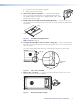


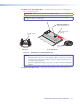

16. Attach the speaker wires to the captive screw connector —
ATTENTION: Do not tin the wires. Tinned wires do not remain tight in the captive
screws and can break easily after several bends.
Number of Wires per Connection Point Maximum Wire Gauge
1 12 AWG
2 16 AWG
4 18 AWG
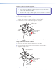
Attach the speaker wires to the included four-pole captive screw connector using one of
the following methods:
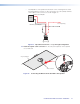
• Wiring a Single Speaker: Connect the wires to the captive screw connectors of
the speakers as shown in figure 12. Be sure to tighten the screws.
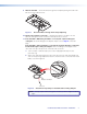
Wiring a Single Speaker
Speaker 1
IN
–
LOOP
–
IN
+
LOOP
+
(Red)
(Black)
Power Amplifier
Figure 12. Wiring a Single Speaker
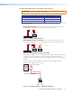
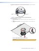
• Wiring Multiple Speakers in Parallel: Connect the wires to the captive screw
connectors of the speakers, as shown in figure 13. Be sure to tighten the screws.
Wiring Multiple Speakers in Parallel
Speaker 1
Speaker 2
IN
–
LOOP
–
IN
+
LOOP
+
IN
–
LOOP
–
IN
+
LOOP
+
(Black)
(Red)
(Red)
(Black)
Power Amplifier
(Black)
(Red)
Figure 13. Wiring Multiple Speakers in Parallel
In the parallel configuration, all of the speakers downstream of the one being tested
continue to function even when it is disconnected. This is especially useful in
installations where the system can never be completely down, such as in a hospital
setting.
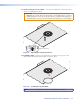
The source signal can be tested by connecting to the inner + (IN) and – (IN)
terminals of the captive screw connector.
Signal Test Points
Red Wire (+) from Amplifier
Black Wire (-) from Amplifier
Amplifier
Test Points
Figure 14. Signal Test Points — Parallel Configuration
CS 26T and CS 120P User Guide • Installation 9