
User's Manual Part 2

22 Installing the Extricom WLAN System
Connecting the Switch and Access Points
Extricom’s switch is connected to the wired LAN and the APs that are located throughout the
enterprise.
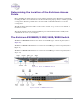
To connect the switch and access points:
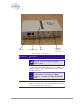
1. Using a CAT-5e/6 100/1000Mbps cable, connect the switch RJ-45 LAN connector (located on
the front panel of the switch, (refer to Figure 12) to the LAN switch.
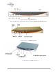
2. Using a CAT-5e/6 cable, connect each AP (refer to Figure 12) to one of the switch’s RJ-45
WLAN connectors. For those APs located over 100 meters from the switch, an Extricom
EXRE-10 Range Extender should be used.
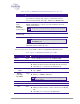
3. Connect the power cable to the power connector located on the rear panel of the switch, and
plug the other end of the power cable into a power source.
4. Verify that the Power LEDs on both the switch and connected APs are green.
Additional APs can be connected/disconnected while the switch is active.
Mounting the Access Points (Optional)
Extricom APs can be mounted on the wall. To mount the APs, you will need two stainless steel pan
head 8x1-1/4" self-tapping Phillips screws.
To mount the Access Points:
1. Place the installation template (refer to Access Point Mounting Template on page 70) on the
wall where you want to mount the AP.
2. Mark the "Point for Drilling" locations on the wall.
3. Screw the two stainless steel pan head 8x1-1/4" self-tapping Phillips screws into the wall
leaving enough of the screws protruding to enable you to hook the AP over the screw.
4. Align the holes on the back of the AP with the screws and slip the AP into place.
Position the AP so that the connectors are on the bottom left corner of the AP.