
Installation Guide
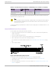
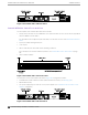
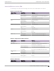
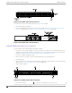
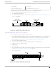
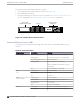
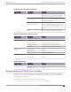
Table Of Contents
- Table of Contents
- Preface
- Summit Switches
- Overview of the Switches
- Summit X150 Series Switches
- Summit X250e Series Switches
- Summit X250e-24t Switch Ports and Slots
- Summit X250e-24tDC Switch Ports and Slots
- Summit X250e-24x Switch Ports and Slots
- Summit X250e-24xDC Switch Ports and Slots
- Summit X250e-24p Switch Ports and Slots
- Summit X250e-48t Switch Ports and Slots
- Summit X250e-48tDC Switch Ports and Slots
- Summit X250e-48p Switch Ports and Slots
- Summit X250e-48p Power Supplies
- Summit X250e Series Switch LEDs
- Summit X350 Series Switches
- Summit X430 Series Switches
- Summit X440 Series Switches
- Summit X440-8t Switch Ports and Slots
- Summit X440-8p Switch Ports and Slots
- Summit X440-24t Switch Ports and Slots
- Summit X440-24tDC Switch Ports and Slots
- Summit X440-24t-10G Switch Ports and Slots
- Summit X440-L2-24t Switch Ports and Slots
- Summit X440-24x Switch Ports and Slots
- Summit X440-24x-10G Switch Ports and Slots
- Summit X440-24p Switch Ports and Slots
- Summit X440-24p-10G Switch Ports and Slots
- Summit X440-48t Switch Ports and Slots
- Summit X440-48tDC Switch Ports and Slots
- Summit X440-48t-10G Switch Ports and Slots
- Summit X440-L2-48t Switch Ports and Slots
- Summit X440-48p Switch Ports and Slots
- Summit X440-48p-10G Switch Ports and Slots
- Summit X440 Series Switch LEDs
- Summit X450, X450a, and X450e Series Switches
- ExtremeSwitching X450-G2 Series Switches
- ExtremeSwitching X450-G2-24t-GE4 Switch Ports and Slots
- ExtremeSwitching X450-G2-24t-10GE4 Switch Ports and Slots
- ExtremeSwitching X450-G2-24p-GE4 Switch Ports and Slots
- ExtremeSwitching X450-G2-24p-10GE4 Switch Ports and Slots
- ExtremeSwitching X450-G2-48t-GE4 Switch Ports and Slots
- ExtremeSwitching X450-G2-48t-10GE4 Switch Ports and Slots
- ExtremeSwitching X450-G2-48p-GE4 Switch Ports and Slots
- ExtremeSwitching X450-G2-48p-10GE4 Switch Ports and Slots
- ExtremeSwitching X450-G2 Series Switch LEDs
- Summit X460 Series Switches
- ExtremeSwitching X460-G2 Series Switches
- ExtremeSwitching X460-G2-24t-GE4 Switch Ports and Slots
- ExtremeSwitching X460-G2-24t-10GE4 Switch Ports and Slots
- ExtremeSwitching X460-G2-24x-10GE4 Switch Ports and Slots
- ExtremeSwitching X460-G2-24p-GE4 Switch Ports and Slots
- ExtremeSwitching X460-G2-24p-10GE4 Switch Ports and Slots
- ExtremeSwitching X460-G2-48t-GE4 Switch Ports and Slots
- ExtremeSwitching X460-G2-48t-10GE4 Switch Ports and Slots
- ExtremeSwitching X460-G2-48x-10GE4 Switch Ports and Slots
- Summit X460-G2-48p-GE4 Switch Ports and Slots
- ExtremeSwitching X460-G2-48p-10GE4 Switch Ports and Slots
- ExtremeSwitching X460-G2 Series Switch LEDs
- Summit X480 Series Switches
- Summit X650 Series Switches
- Summit X670 Series Switches
- ExtremeSwitching X670-G2 Series Switches
- ExtremeSwitching X770 Series Switches
- Pluggable Interfaces for the Switches
- Concept Title
- Power Supplies for Use with Your Switch
- External Power Supplies
- EPS-150DC External Power Module (with EPS-T2)
- EPS-160 External Power Module (with EPS-T)
- EPS-500 External Power Supply Unit
- EPS-600LS External Power Module
- EPS-C2 Redundant Power System
- EPS-LD External Power Supply Unit
- X450 and X250 PoE Redundant Power Configurations
- RPS-90 Redundant Power Supply
- RPS-150XT Redundant Power Supply
- RPS-500p Redundant Power Supply
- STK-RPS-150PS Redundant Power Supply
- STK-RPS-1005PS Redundant Power Supply
- VX-RPS-1000 Redundant Power Supply
- Replaceable Internal Power Supplies
- Summit 300 W AC and DC Power Supplies
- Summit 350 W AC Power Supplies
- Summit 450 W AC and DC Power Supplies
- Summit 550 W AC and DC Power Supplies
- Summit 715 W AC Power Supplies
- Summit 750 W AC Power Supply
- 750 W AC and DC Power Supplies
- Summit 770 W AC Power Supplies
- Summit 850 W AC and DC Power Supplies
- Summit 1100 W AC Power Supplies
- Summit 1100 W DC Power Supplies
- 2000 W AC Power Supply
- Displaying the Status of Installed Power Supplies
- External Power Supplies
- Expansion Modules
- Site Preparation
- Building Stacks
- Introduction to Stacking
- Planning to Create Your Stack
- Enabling and Disabling the Stacking-Support Option
- Recommendations for Placing Switches for Stacked Operation
- Recommendations for Configuring Stacks
- Stacking Considerations for Each Switch Model
- Summit X250e and X450a/e Stacking
- Summit X440 Stacking
- X440-G2 Stacking
- X450-G2 Stacking
- Summit X460 Stacking
- X460-G2 Stacking
- ExtremeSwitching X465 Stacking
- Summit X480 Stacking
- X590 Stacking
- X620 Stacking
- Summit X650 Stacking
- Summit X670 Stacking
- X670-G2 Stacking
- X690 Stacking
- ExtremeSwitching X695 Stacking
- Summit X770 Stacking
- X870 Stacking
- Selecting Native and Alternate Stacking Ports
- Combining Switches from Different Series
- Selecting Stacking Cables
- Using the Extreme Stacking Tool
- Setting up the Physical Stack
- Connecting the Switches to Form the Stack Ring
- Connecting Stacking Cables
- Connecting a SummitStack Cable to a Stacking Port
- Connecting a SummitStack 128G Cable
- Connecting a SummitStack 128G/20G Stacking Cable
- Connecting a SummitStack 128G/64G Stacking Cable
- Connecting a SummitStack 64G Stacking Cable
- Connecting a SummitStack 64G/20G Stacking Cable
- Connecting Active or Passive QSFP+ Cables
- Connecting Your Stack to the Management Network
- Installing Switches
- Safety Considerations for Installing Switches
- Pre-installation Requirements
- Installing a Summit Family Switch
- Installing a Summit X430-8p or X440-8t Switch in a Rack
- Installing a Summit X450-G2 Switch in a Rack
- Installing a Summit X460 Switch in a Rack
- Installing a Summit X460-G2 Switch in a Rack
- Installing a Summit X480 Switch in a Rack
- Installing a Summit X650 Switch in a Rack
- Installing a Summit X670 Switch in a Rack
- Installing a Summit X670-G2 Switch in a Rack
- Installing a Summit X770 Switch in a Rack
- Installing Other Summit Switches in a Rack
- Installing Summit Switches in Desktop or Free-Standing Mode
- Connecting AC-Powered Switches to a Power Source
- Connecting DC-Powered Switches to a Power Source
- Installing Internal Power Supplies
- Install a 300 W Internal DC Power Supply
- Install a 450 W or 550 W Internal DC Power Supply
- Required Tools and Materials for Installing a 450 W or 550 W DC Power Supply
- Preparing the Cables for a 450 W or 550 W DC Power Supply
- Installing a 450 W or 550 W DC Power Supply
- Connecting the Ground Wire to a 450 W or 550 W DC Power Supply
- Connecting a 450 W or 550 W DC Power Supply to the Source Voltage
- Installing an 850 W Internal DC Power Supply
- Installing Internal AC Power Supplies
- Connecting Network Interface Cables
- Performing Initial Management Tasks
- Installing External Power Supplies
- Safety Considerations for Installing Power Supplies
- Pre-installation Requirements
- Installing an EPS-150DC External Power Module (with EPS-T2)
- Installing an EPS-160 External Power Module (with EPS-T)
- Installing an EPS-500 External Power Supply Unit
- Installing an EPS-600LS External Power Module
- Installing an EPS-C2 Power Supply
- Installing an EPS-LD External Power Supply
- Installing an RPS-150XT Redundant Power Supply
- Installing an RPS-500p Redundant Power Supply
- Installing an STK-RPS-150PS Redundant Power Supply
- Installing an STK-RPS-1005PS Redundant Power Supply
- Installing a VX-RPS-1000 Redundant Power Supply
- Installing Expansion Modules
- Installing a V300 Virtual Port Extender
- Install a V300 Virtual Port Extender on a Wall
- Install a V300 Virtual Port Extender Under or on a Table Surface
- Install a V300 Virtual Port Extender in a VESA Mount
- Install a V300 in a Single Rack Mount
- Install a V300 in a Dual Rack Mount
- Install a V300 in a DIN Rail Mount
- Install a V300-8P-2T-W Model in a Single or Dual Rack Mount
- Installing a V300-8P-2T-W Model in a DIN Rail Mount
- Connecting the V300 Virtual Port Extender to Power
- Installing a V400 Virtual Port Extender
- Installing an LRM/MACsec Adapter
- Installing a Half-Duplex to Full-Duplex Converter
- Installing a Summit Port Option Card
- Installing an Option Card in Slot B of a Summit X460 Series Switch
- Installing a Versatile Interface Module in a Summit X460, X480, X650, or X670 Series Switch
- Installing a Versatile Interface Module or Clock Module in an X460-G2 Series Switch
- Install a Versatile Interface Module in a VSP 4900 Series Switch
- Install an SSD Module
- Installing a V300 Virtual Port Extender
- Replacing AC Power Supplies
- Replacing a Summit 300 W AC Power Supply
- Replacing a Summit 350 W or 715 W AC Power Supply
- Replacing a Summit 450 W or 550 W AC Power Supply
- Replacing a 750 W AC Power Supply
- Replacing a Summit 770 W AC Power Supply
- Replacing a Summit 850 W AC Power Supply
- Replacing a Summit 1100 W AC Power Supply
- Replace a 2000 W AC Power Supply
- Removing an EPS-LD or EPS-500 Power Supply
- Removing an EPS-160 Power Supply from an EPS-T
- Removing an EPS-600LS Power Module
- Removing an RPS-150XT Redundant Power Supply
- Removing an RPS-500p Redundant Power Supply
- Removing an STK-RPS-150PS Redundant Power Supply
- Removing an STK-RPS-1005PS Redundant Power Supply
- Removing a VX-RPS-1000 Redundant Power Supply
- Replacing DC Power Supplies
- Replacing Fan Modules
- Removing and Replacing Expansion Modules
- Removing or Replacing a V300 Virtual Port Extender
- Removing or Replacing a V400 Virtual Port Extender
- Removing or Replacing an LRM/MACsec Adapter
- Removing or Replacing a Half-Duplex to Full-Duplex Converter
- Replacing a Stacking Module or Option Card in Slot B of a Summit X460 Series Switch
- Replacing an XGM3/XGM3S Series Port Option Card in a Summit X460 Series Switch
- Replacing a Versatile Interface Module (VIM) in a Summit X480, X650 or X670 Series Switch
- Replacing an XGM or XGM2 Series Port Option Card
- Replacing a Versatile Interface Module, Solid-state Drive, or Clock Module in an X460-G2 Series or X465 Series Switch
- Removing Switches from Service
- Safety and Regulatory Information
- Considerations Before Installing
- General Safety Precautions
- Maintenance Safety
- Fiber Optic Ports and Optical Safety
- Cable Routing for LAN Systems
- Installing Power Supply Units and Connecting Power
- Selecting Power Supply Cords
- Battery Notice
- Battery Warning - Taiwan
- EMC Warnings
- Japan (VCCI Class A)
- Korea EMC Statement
- Technical Specifications
- Summit X150 Series Switches Technical Specifications
- Summit X250e Series Switches Technical Specifications
- Summit X350 Series Switches Technical Specifications
- Summit X430 Series Switches Technical Specifications
- Summit X440 Series Switches Technical Specifications
- Summit X450 Series Switches Technical Specifications
- Summit X450a Series Switches Technical Specifications
- Summit X450e Series Switches Technical Specifications
- ExtremeSwitching X450-G2 Series Switches Technical Specifications
- Summit X460 Series Switches Technical Specifications
- ExtremeSwitching X460-G2 Series Switches Technical Specifications
- Summit X480 Series Switches Technical Specifications
- Summit X650 Series Switches Technical Specifications
- Summit X670 Series Switches Technical Specifications
- Summit X670-G2 Series Switches Technical Specifications
- Summit X770 Series Switches Technical Specifications
- STK-RPS-150PS and RPS Shelves Technical Specifications
- Summit 300 W Power Supplies Technical Specifications
- Summit 350 W Power Supplies Technical Specifications
- Summit 450 W Power Supplies Technical Specifications
- Summit 550 W Power Supplies Technical Specifications
- Summit 550 W Power Supplies for X670-G2 Switches
- Summit 715 W Power Supplies Technical Specifications
- 750 W Power Supplies Technical Specifications
- Summit 850 W Power Supplies Technical Specifications
- Summit 1100 W Power Supplies Technical Specifications
- Summit External Power Supplies Technical Specifications
- EPS-C2 Redundant Power Supply Technical Specifications
- RPS-500p Redundant Power Supply Technical Specifications
- Power Cord Requirements for AC-Powered Switches and AC Power Supplies
- Console Connector Pinouts
- EMC Warnings
- Japan (VCCI Class A)
- Korea EMC Statement
- Glossary
- Index

Table 54: Front Panel LEDs (continued)
Label or Type Color/State Meaning
MD Steady green The motion detector feature is enabled. This
LED stays lit if the motion detector feature
shuts down the other LEDs on the switch.
Blinking green (other switch
LEDs are also lit)
Motion has been detected. The green blinking
continues for a few seconds, and then the MD
LED lights steady green.
Blinking amber (other
switch LEDs are o)
Motion has been detected. The motion
detector feature turns on the other switch
LEDs. The amber blinking continues for a few
seconds, and then the MD LED lights steady
green.
O The motion detector feature is disabled.
Table 55: 2-digit Stack number Indicator
Label or Type Color/State Meaning
Left digit (1) Reserved for future use.
Right digit (1 – 8) Indicates the position of this switch in the SummitStack configuration.
Upper half blinking This switch is the stack master node.
Lower half blinking This switch is the stack backup node.
Lit steadily This switch is a standby node in the stack.
Ethernet Ports
1 – 48
Steady green Link OK
Blinking green Activity
O No link or port disabled.
Management Port Steady green Link OK
Blinking green Activity
Table 56: Back Panel
Label or Type Color/State Meaning
QSFP+ port LED (on
installed VIM3 module)
Steady green Link OK
Blinking green Activity
ExtremeSwitching X670-G2 Series Switches
The X670-G2 series switches have 48 or 72 front-panel Ethernet ports that can provide 10-gigabit
Ethernet connectivity using installable SFP+ optical modules. In addition, the X670-G2-48x-4q series
switches oer four QSFP+ ports.
The X670-G2 series switches include the following base models:
• ExtremeSwitching X670-G2-48x-4q Switch Ports and Slots on page 151
Summit Switches
ExtremeSwitching X670-G2 Series Switches
Summit Family Hardware Installation Guide 149