
Installation Guide
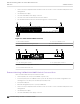
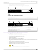
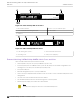
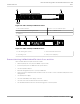
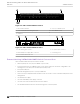
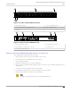
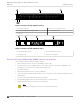
Table Of Contents
- Table of Contents
- Preface
- Summit Switches
- Overview of the Switches
- Summit X150 Series Switches
- Summit X250e Series Switches
- Summit X250e-24t Switch Ports and Slots
- Summit X250e-24tDC Switch Ports and Slots
- Summit X250e-24x Switch Ports and Slots
- Summit X250e-24xDC Switch Ports and Slots
- Summit X250e-24p Switch Ports and Slots
- Summit X250e-48t Switch Ports and Slots
- Summit X250e-48tDC Switch Ports and Slots
- Summit X250e-48p Switch Ports and Slots
- Summit X250e-48p Power Supplies
- Summit X250e Series Switch LEDs
- Summit X350 Series Switches
- Summit X430 Series Switches
- Summit X440 Series Switches
- Summit X440-8t Switch Ports and Slots
- Summit X440-8p Switch Ports and Slots
- Summit X440-24t Switch Ports and Slots
- Summit X440-24tDC Switch Ports and Slots
- Summit X440-24t-10G Switch Ports and Slots
- Summit X440-L2-24t Switch Ports and Slots
- Summit X440-24x Switch Ports and Slots
- Summit X440-24x-10G Switch Ports and Slots
- Summit X440-24p Switch Ports and Slots
- Summit X440-24p-10G Switch Ports and Slots
- Summit X440-48t Switch Ports and Slots
- Summit X440-48tDC Switch Ports and Slots
- Summit X440-48t-10G Switch Ports and Slots
- Summit X440-L2-48t Switch Ports and Slots
- Summit X440-48p Switch Ports and Slots
- Summit X440-48p-10G Switch Ports and Slots
- Summit X440 Series Switch LEDs
- Summit X450, X450a, and X450e Series Switches
- ExtremeSwitching X450-G2 Series Switches
- ExtremeSwitching X450-G2-24t-GE4 Switch Ports and Slots
- ExtremeSwitching X450-G2-24t-10GE4 Switch Ports and Slots
- ExtremeSwitching X450-G2-24p-GE4 Switch Ports and Slots
- ExtremeSwitching X450-G2-24p-10GE4 Switch Ports and Slots
- ExtremeSwitching X450-G2-48t-GE4 Switch Ports and Slots
- ExtremeSwitching X450-G2-48t-10GE4 Switch Ports and Slots
- ExtremeSwitching X450-G2-48p-GE4 Switch Ports and Slots
- ExtremeSwitching X450-G2-48p-10GE4 Switch Ports and Slots
- ExtremeSwitching X450-G2 Series Switch LEDs
- Summit X460 Series Switches
- ExtremeSwitching X460-G2 Series Switches
- ExtremeSwitching X460-G2-24t-GE4 Switch Ports and Slots
- ExtremeSwitching X460-G2-24t-10GE4 Switch Ports and Slots
- ExtremeSwitching X460-G2-24x-10GE4 Switch Ports and Slots
- ExtremeSwitching X460-G2-24p-GE4 Switch Ports and Slots
- ExtremeSwitching X460-G2-24p-10GE4 Switch Ports and Slots
- ExtremeSwitching X460-G2-48t-GE4 Switch Ports and Slots
- ExtremeSwitching X460-G2-48t-10GE4 Switch Ports and Slots
- ExtremeSwitching X460-G2-48x-10GE4 Switch Ports and Slots
- Summit X460-G2-48p-GE4 Switch Ports and Slots
- ExtremeSwitching X460-G2-48p-10GE4 Switch Ports and Slots
- ExtremeSwitching X460-G2 Series Switch LEDs
- Summit X480 Series Switches
- Summit X650 Series Switches
- Summit X670 Series Switches
- ExtremeSwitching X670-G2 Series Switches
- ExtremeSwitching X770 Series Switches
- Pluggable Interfaces for the Switches
- Concept Title
- Power Supplies for Use with Your Switch
- External Power Supplies
- EPS-150DC External Power Module (with EPS-T2)
- EPS-160 External Power Module (with EPS-T)
- EPS-500 External Power Supply Unit
- EPS-600LS External Power Module
- EPS-C2 Redundant Power System
- EPS-LD External Power Supply Unit
- X450 and X250 PoE Redundant Power Configurations
- RPS-90 Redundant Power Supply
- RPS-150XT Redundant Power Supply
- RPS-500p Redundant Power Supply
- STK-RPS-150PS Redundant Power Supply
- STK-RPS-1005PS Redundant Power Supply
- VX-RPS-1000 Redundant Power Supply
- Replaceable Internal Power Supplies
- Summit 300 W AC and DC Power Supplies
- Summit 350 W AC Power Supplies
- Summit 450 W AC and DC Power Supplies
- Summit 550 W AC and DC Power Supplies
- Summit 715 W AC Power Supplies
- Summit 750 W AC Power Supply
- 750 W AC and DC Power Supplies
- Summit 770 W AC Power Supplies
- Summit 850 W AC and DC Power Supplies
- Summit 1100 W AC Power Supplies
- Summit 1100 W DC Power Supplies
- 2000 W AC Power Supply
- Displaying the Status of Installed Power Supplies
- External Power Supplies
- Expansion Modules
- Site Preparation
- Building Stacks
- Introduction to Stacking
- Planning to Create Your Stack
- Enabling and Disabling the Stacking-Support Option
- Recommendations for Placing Switches for Stacked Operation
- Recommendations for Configuring Stacks
- Stacking Considerations for Each Switch Model
- Summit X250e and X450a/e Stacking
- Summit X440 Stacking
- X440-G2 Stacking
- X450-G2 Stacking
- Summit X460 Stacking
- X460-G2 Stacking
- ExtremeSwitching X465 Stacking
- Summit X480 Stacking
- X590 Stacking
- X620 Stacking
- Summit X650 Stacking
- Summit X670 Stacking
- X670-G2 Stacking
- X690 Stacking
- ExtremeSwitching X695 Stacking
- Summit X770 Stacking
- X870 Stacking
- Selecting Native and Alternate Stacking Ports
- Combining Switches from Different Series
- Selecting Stacking Cables
- Using the Extreme Stacking Tool
- Setting up the Physical Stack
- Connecting the Switches to Form the Stack Ring
- Connecting Stacking Cables
- Connecting a SummitStack Cable to a Stacking Port
- Connecting a SummitStack 128G Cable
- Connecting a SummitStack 128G/20G Stacking Cable
- Connecting a SummitStack 128G/64G Stacking Cable
- Connecting a SummitStack 64G Stacking Cable
- Connecting a SummitStack 64G/20G Stacking Cable
- Connecting Active or Passive QSFP+ Cables
- Connecting Your Stack to the Management Network
- Installing Switches
- Safety Considerations for Installing Switches
- Pre-installation Requirements
- Installing a Summit Family Switch
- Installing a Summit X430-8p or X440-8t Switch in a Rack
- Installing a Summit X450-G2 Switch in a Rack
- Installing a Summit X460 Switch in a Rack
- Installing a Summit X460-G2 Switch in a Rack
- Installing a Summit X480 Switch in a Rack
- Installing a Summit X650 Switch in a Rack
- Installing a Summit X670 Switch in a Rack
- Installing a Summit X670-G2 Switch in a Rack
- Installing a Summit X770 Switch in a Rack
- Installing Other Summit Switches in a Rack
- Installing Summit Switches in Desktop or Free-Standing Mode
- Connecting AC-Powered Switches to a Power Source
- Connecting DC-Powered Switches to a Power Source
- Installing Internal Power Supplies
- Install a 300 W Internal DC Power Supply
- Install a 450 W or 550 W Internal DC Power Supply
- Required Tools and Materials for Installing a 450 W or 550 W DC Power Supply
- Preparing the Cables for a 450 W or 550 W DC Power Supply
- Installing a 450 W or 550 W DC Power Supply
- Connecting the Ground Wire to a 450 W or 550 W DC Power Supply
- Connecting a 450 W or 550 W DC Power Supply to the Source Voltage
- Installing an 850 W Internal DC Power Supply
- Installing Internal AC Power Supplies
- Connecting Network Interface Cables
- Performing Initial Management Tasks
- Installing External Power Supplies
- Safety Considerations for Installing Power Supplies
- Pre-installation Requirements
- Installing an EPS-150DC External Power Module (with EPS-T2)
- Installing an EPS-160 External Power Module (with EPS-T)
- Installing an EPS-500 External Power Supply Unit
- Installing an EPS-600LS External Power Module
- Installing an EPS-C2 Power Supply
- Installing an EPS-LD External Power Supply
- Installing an RPS-150XT Redundant Power Supply
- Installing an RPS-500p Redundant Power Supply
- Installing an STK-RPS-150PS Redundant Power Supply
- Installing an STK-RPS-1005PS Redundant Power Supply
- Installing a VX-RPS-1000 Redundant Power Supply
- Installing Expansion Modules
- Installing a V300 Virtual Port Extender
- Install a V300 Virtual Port Extender on a Wall
- Install a V300 Virtual Port Extender Under or on a Table Surface
- Install a V300 Virtual Port Extender in a VESA Mount
- Install a V300 in a Single Rack Mount
- Install a V300 in a Dual Rack Mount
- Install a V300 in a DIN Rail Mount
- Install a V300-8P-2T-W Model in a Single or Dual Rack Mount
- Installing a V300-8P-2T-W Model in a DIN Rail Mount
- Connecting the V300 Virtual Port Extender to Power
- Installing a V400 Virtual Port Extender
- Installing an LRM/MACsec Adapter
- Installing a Half-Duplex to Full-Duplex Converter
- Installing a Summit Port Option Card
- Installing an Option Card in Slot B of a Summit X460 Series Switch
- Installing a Versatile Interface Module in a Summit X460, X480, X650, or X670 Series Switch
- Installing a Versatile Interface Module or Clock Module in an X460-G2 Series Switch
- Install a Versatile Interface Module in a VSP 4900 Series Switch
- Install an SSD Module
- Installing a V300 Virtual Port Extender
- Replacing AC Power Supplies
- Replacing a Summit 300 W AC Power Supply
- Replacing a Summit 350 W or 715 W AC Power Supply
- Replacing a Summit 450 W or 550 W AC Power Supply
- Replacing a 750 W AC Power Supply
- Replacing a Summit 770 W AC Power Supply
- Replacing a Summit 850 W AC Power Supply
- Replacing a Summit 1100 W AC Power Supply
- Replace a 2000 W AC Power Supply
- Removing an EPS-LD or EPS-500 Power Supply
- Removing an EPS-160 Power Supply from an EPS-T
- Removing an EPS-600LS Power Module
- Removing an RPS-150XT Redundant Power Supply
- Removing an RPS-500p Redundant Power Supply
- Removing an STK-RPS-150PS Redundant Power Supply
- Removing an STK-RPS-1005PS Redundant Power Supply
- Removing a VX-RPS-1000 Redundant Power Supply
- Replacing DC Power Supplies
- Replacing Fan Modules
- Removing and Replacing Expansion Modules
- Removing or Replacing a V300 Virtual Port Extender
- Removing or Replacing a V400 Virtual Port Extender
- Removing or Replacing an LRM/MACsec Adapter
- Removing or Replacing a Half-Duplex to Full-Duplex Converter
- Replacing a Stacking Module or Option Card in Slot B of a Summit X460 Series Switch
- Replacing an XGM3/XGM3S Series Port Option Card in a Summit X460 Series Switch
- Replacing a Versatile Interface Module (VIM) in a Summit X480, X650 or X670 Series Switch
- Replacing an XGM or XGM2 Series Port Option Card
- Replacing a Versatile Interface Module, Solid-state Drive, or Clock Module in an X460-G2 Series or X465 Series Switch
- Removing Switches from Service
- Safety and Regulatory Information
- Considerations Before Installing
- General Safety Precautions
- Maintenance Safety
- Fiber Optic Ports and Optical Safety
- Cable Routing for LAN Systems
- Installing Power Supply Units and Connecting Power
- Selecting Power Supply Cords
- Battery Notice
- Battery Warning - Taiwan
- EMC Warnings
- Japan (VCCI Class A)
- Korea EMC Statement
- Technical Specifications
- Summit X150 Series Switches Technical Specifications
- Summit X250e Series Switches Technical Specifications
- Summit X350 Series Switches Technical Specifications
- Summit X430 Series Switches Technical Specifications
- Summit X440 Series Switches Technical Specifications
- Summit X450 Series Switches Technical Specifications
- Summit X450a Series Switches Technical Specifications
- Summit X450e Series Switches Technical Specifications
- ExtremeSwitching X450-G2 Series Switches Technical Specifications
- Summit X460 Series Switches Technical Specifications
- ExtremeSwitching X460-G2 Series Switches Technical Specifications
- Summit X480 Series Switches Technical Specifications
- Summit X650 Series Switches Technical Specifications
- Summit X670 Series Switches Technical Specifications
- Summit X670-G2 Series Switches Technical Specifications
- Summit X770 Series Switches Technical Specifications
- STK-RPS-150PS and RPS Shelves Technical Specifications
- Summit 300 W Power Supplies Technical Specifications
- Summit 350 W Power Supplies Technical Specifications
- Summit 450 W Power Supplies Technical Specifications
- Summit 550 W Power Supplies Technical Specifications
- Summit 550 W Power Supplies for X670-G2 Switches
- Summit 715 W Power Supplies Technical Specifications
- 750 W Power Supplies Technical Specifications
- Summit 850 W Power Supplies Technical Specifications
- Summit 1100 W Power Supplies Technical Specifications
- Summit External Power Supplies Technical Specifications
- EPS-C2 Redundant Power Supply Technical Specifications
- RPS-500p Redundant Power Supply Technical Specifications
- Power Cord Requirements for AC-Powered Switches and AC Power Supplies
- Console Connector Pinouts
- EMC Warnings
- Japan (VCCI Class A)
- Korea EMC Statement
- Glossary
- Index

CONSOLE
Summit
™
X450-G2-24p-GE4
GbES FP
25
27
28
26
MGT FAN P1 P2 S
1 2 3 4 5 6 7 8 9
10 11 12 13 14 15 16
18
17 19
20
21
22
23
24
CLK ACT LINK
S2
STACK NO.
Management
5
3
4
1
2
Figure 94: X450-G2-24p-GE4 Front Panel
1 = Stack number indicator 4 = PoE+ 10/100/1000BASE-T ports
2 = Console port/Ethernet management port 5 = SFP 1G ports
3 = USB port
PSU -2PS
IN.OK
AIR OUT
(AFO)
OUT. OK
115V-240V- 12-6A 50-60Hz
CLEI LABEL
U-1
SummitStack-V84
431 2
Figure 95: X450-G2-24p-GE4 Rear Panel
1 = 21 Gb stacking ports (QSFP+)
3 = Front-to-back fan module slot
2 = Grounding screw 4 = PoE+ power supply bays
ExtremeSwitching X450-G2-24p-10GE4 Switch Ports and Slots
X450-G2-24p-10GE4 switch ports and slots include:
• 24 front panel PoE+ ports of 10/100/1000BASE-T (ports 1–24).
• Four front panel ports of 10GBASE-X SFP+ (ports 25–28, with ports 27 and 28
configurable to be
stacking ports). The SFP+ ports are dual speed (1 Gb/10 Gb).
• Front panel USB port.
• Ethernet management port 1 x 10/100/1000BASE-T.
• Serial console port implemented as an RJ45 connector used to connect a terminal and perform local
management.
• One rear slot for fan module with front-to-back
airflow.
• Two dedicated QSFP-form factor 21 Gb stacking ports on the rear panel.
• Rear dual power supply slots with front-to-back airflow.
Note
Unused power supply slots must be covered with blank panels.
ExtremeSwitching X450-G2-24p-10GE4 Switch Ports
and Slots Summit Switches
106 Summit Family Hardware Installation Guide