WM-4T1i Module Installation and User Guide Extreme Networks, Inc. 3585 Monroe Street Santa Clara, California 95051 (888) 257-3000 http://www.extremenetworks.com Published: June 2001 Part number: 100095-00 Rev.
©2001 Extreme Networks, Inc. All rights reserved. Extreme Networks and BlackDiamond are registered trademarks of Extreme Networks, Inc. in the United States and certain other jurisdictions.
Contents Preface 1 2 WM-4T1i Installation and User Guide Introduction v Conventions vi Related Publications vii Installing the WM-4T1i Module Overview 1-1 Installing the WM-4T1i Module 1-2 Ports and Connectors WM-4T1i Module LEDs 1-3 1-3 Installing the WM-4T1i Module Software 1-5 Configuring the T1 Physical Link Overview 2-1 Configuring T1 Physical link Alarms Cable length Clock Source Facility Data Link Framing Inband Loopback Detection Linecoding 2-1 2-2 2-2 2-3 2-3 2-4 2-4 2-4 iii
Yellow Alarms T1 Port Configuration Commands 2-5 2-5 Monitoring T1 Physical Link Loopback Near-end Loopback Modes Far-End Loopback Modes Enabling Loopback Mode Disabling Loopback Mode T1 Port Monitoring Commands 3 2-6 2-6 2-7 2-8 2-10 2-10 2-10 Configuring PPP and MLPPP Overview 3-1 Multilink PPP and Multilink Groups 3-2 Configuring a PPP/MLPPP Link Authentication PPP Link Username PPP User Accounts Encapsulation PPP/MLPPP Configuration Commands 3-3 3-3 3-3 3-4 3-4 3-5 Monitoring PPP/MLPPP Links
Preface This Preface provides an overview of this guide, describes guide conventions, and lists other publications that may be useful. Introduction This guide provides the required information to install the WM-4T1i module in an Alpine 3800 series switch from Extreme Networks and perform the initial module configuration tasks. This guide is intended for use by network administrators who are responsible for installing and setting up network equipment.
Conventions Table 1 and Table 2 list conventions that are used throughout this guide. Table 1: Notice Icons Icon Notice Type Alerts you to... Note Important features or instructions. Caution Risk of personal injury, system damage, or loss of data. Warning Risk of severe personal injury. Table 2: Text Conventions Convention Description Screen displays This typeface indicates command syntax, or represents information as it appears on the screen.
Related Publications Related Publications The publications related to this one are: • ExtremeWare™ release notes • ExtremeWare Software User Guide • Alpine 3800 Series Switch Hardware Installation Guide • Alpine Module Installation Note Documentation for Extreme Networks products is available on the World Wide Web at the following location: http://www.extremenetworks.
viii WM-4T1i Module Installation and User Guide
1 Installing the WM-4T1i Module This chapter covers the following topics: • Installing the WM-4T1i Module on page 1-2 • Ports and Connectors on page 1-3 • WM-4T1i Module LEDs on page 1-3 • Installing the WM-4T1i Module Software on page 1-5 Overview The Extreme Networks WM-4T1i module is an four-port T1 module that can be configured to use Multilink PPP to aggregate Ethernet traffic across multiple T1 physical links. The module has two 10/100 Mbps Ethernet ports.
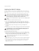
Installing the WM-4T1i Module Installing the WM-4T1i Module All Alpine ™ 3800 series switch module cards (SMMi modules and I/O modules) are hot-swappable. You do not need to power off the system to remove or insert a module card. Caution: Service to Alpine modules should be performed by trained service personnel only.
Ports and Connectors Note: Tighten the screws before inserting additional modules. If you insert additional modules before tightening the screws, you might unseat modules that you have not secured. Caution: You can only install I/O modules in the slots labeled Slot 1 through Slot 4 on the Alpine 3804, or Slot 1 through Slot 8 on the Alpine 3808. Forceful insertion can damage the I/O module and the connector pins on the backplane. Ports and Connectors The WM-4T1i module is show in Figure 1-1.
Installing the WM-4T1i Module Figure 1-2: WM-4T1i LEDs Table 1-1 describes the LED behavior on the WM-4T1i module.
Installing the WM-4T1i Module Software The slowly blinking LEDs cycle once per second. The rapidly blinking LEDs cycle twice a second. Installing the WM-4T1i Module Software Once the WM-4T1i module is installed in the chassis, you must download an image file to the module. The image file contains the executable code that runs on the module. As new versions of the image are released, you should upgrade the software running on your module.
Installing the WM-4T1i Module use image [primary | secondary] 1-6 WM-4T1i Module Installation and User Guide
2 Configuring the T1 Physical Link This chapter covers the following topics: • Configuring T1 Physical link on page 2-1 • Monitoring T1 Physical Link on page 2-6 Overview T1 is a mature technology originally developed for voice telephone transmission. It was used to aggregate a number of voice lines into a single connection to the telephone network. Today T1 is also widely used to transmit digital data using widely available equipment and established wiring commonly available in diverse locations.
Configuring the T1 Physical Link • Clock Source • Facility Data Link • Framing • Inband Loopback Detection • Linecoding • Yellow Alarms Alarms The T1 standard, ANSI T1.403, Bellcore TR-54016 and others, defines red, yellow, and blue alarms. A red alarm occurs when the T1 signal is lost or an out of frame error occurs.
Configuring T1 Physical link cablelength command allows you to control the transmitter signal level for your conditions. Typically, your service provider will suggest the correct level. For short haul connections (less then 700 feet) the typical equipment uses less sensitive receivers. The transmitter level is usually set by selecting a cable length in feet, from the following values: 133, 266, 399, 533 or 655. Choose the next higher value if your cable length does not match one of the values.
Configuring the T1 Physical Link are ignored when a port is configured for SF framing. See “Framing” for information on configuring framing. The two standards supported for FDL are ATT, described by the ATT 54016 specification, and ANSI, described by the T1.403 standard. The default value is off. To configure FDL, use the following command: config ports t1 fdl [off | att | ansi] Framing Framing is used to synchronize data transmission on the T1 line.
Configuring T1 Physical link Yellow Alarms A yellow alarm occurs on a device when its signal is not received at the remote end. It is also called a Remote Alarm Indication (RAI). You can disable detection and generation of yellow alarms for a T1 port.
Configuring the T1 Physical Link Monitoring T1 Physical Link T1 devices have a built-in facility designed for troubleshooting the physical link, called loopback. The T1 link can also be monitored using show commands to display the current configuration of the link, any alarms on the link, link statistics, and link errors. Loopback The T1 device can be set up to loopback, that is, return a transmitted signal back to the sender so it can be compared with the original.
Monitoring T1 Physical Link Near-end Loopback Modes The near-end of the link can be enabled for the following three loopback modes: • Local • Network Line • Network Payload The local loopback mode reflects the data stream internally to the near-end. The network line loopback mode reflects the signal to the far-end. The network payload mode reflects the data carried in the signal and regenerates framing information back to the far-end.
Configuring the T1 Physical Link Local T1 Port Remote T1 Port Data out Data in Data in Data out Framer Framer XM_012 Figure 2-3: Network line loopback mode Network Line Loopback Mode. When the local port is enabled for network line loopback mode, the received signal is sent back to the remote end without reframing the data. This mode primarily tests the integrity of the line from the remote side.
Monitoring T1 Physical Link The remote line mode reflects the received signal back to the near-end. The remote payload mode reflects the data and regenerates the framing information back to the near-end. Local T1 Port Remote T1 Port Data in Data out Data out Data in Framer Framer XM_014 Figure 2-5: Remote line loopback mode Remote Line Loopback Mode.
Configuring the T1 Physical Link remote end removes the framing bits from the received signal and recovers the transmitted data. This same data is then reframed and transmitted back to the local end.
Monitoring T1 Physical Link Table 2-2: T1 Port Monitoring Commands (continued) Command Description show ports {} t1 errors [near-end | far-end] [totals | intervals | current] Displays current and past errors. show ports {} t1 info Displays the port configuration and status.
Configuring the T1 Physical Link 2-12 WM-4T1i Module Installation and User Guide
3 Configuring PPP and MLPPP This chapter covers the following topics: • Multilink PPP and Multilink Groups on page 3-2 • Configuring a PPP/MLPPP Link on page 3-3 • Monitoring PPP/MLPPP Links on page 3-6 • PPP/MLPPP Configuration Examples on page 3-6 Overview Point-to-Point Protocol (PPP) is used across the entire range of communication speeds and devices found on the internet.
Configuring PPP and MLPPP Multilink PPP and Multilink Groups Each multilink PPP group is given a name, up to 16 characters in length. All named components of the switch configuration must have unique names, so multilink groups and VLANs cannot have identical names. See the ExtremeWare Software User Guide for more information on allowable names for named components. Components are named using the create command.
Configuring a PPP/MLPPP Link Configuring a PPP/MLPPP Link All of the PPP configuration commands can be used to configure a single port or to configure a multilink group, so the following sections for PPP links also apply to MLPPP links. To configure a PPP/MLPPP link you will need to choose the authentication and encapsulation for the link. If you change the configuration of an enabled PPP or MLPPP link, the changes will not take effect until the link is restarted.
Configuring PPP and MLPPP config ppp user {encrypted} [ports | multilink ] The encrypted keyword is used to hide the password when the switch configuration is displayed, it does not control whether the password is encrypted across the link during authentication. PPP User Accounts When the remote end initiates the link, the local end must verify the authentication information. The local end maintains a list of authorized user accounts and passwords.
Configuring a PPP/MLPPP Link config ppp [bcp [on | off] | ipcp [on | off]] [ports | multilink ] PPP/MLPPP Configuration Commands Table 3-1 describes the commands used to configure a PPP/MLPPP link. Table 3-1: PPP/MLPPP Configuration Commands Command Description config multilink add ports Adds ports to a multilink group. config multilink delete ports Removes ports from a multilink group.
Configuring PPP and MLPPP Table 3-1: PPP/MLPPP Configuration Commands (continued) Command Description restart multilink Restarts multilink group. Configuration changes made to an enable multilink group will not take effect until the group is restarted. unconfig ppp port Resets the port to the default PPP configuration; no authentication and BCP encapsulation. Monitoring PPP/MLPPP Links The following commands monitor the status of the PPP and MLPPP links.
PPP/MLPPP Configuration Examples have the same T1 and PPP configurations. If you change the configuration for a single port, the change will affect the entire group.
Configuring PPP and MLPPP VLAN beta tag = 1001 IP address = 10.10.10.1/24 Multilink ipcp_example encapsulation = IPCP PPP PPP PPP Switch #1 T1 port 4:1 T1 port 4:2 T1 port 4:3 To switch #2 XM_008 Figure 3-2: IPCP multilink example config create config config create config config config enable 3-8 default delete ports 4:1-4:3 vlan beta beta tag 1001 beta ipaddress 10.10.10.
Index Numerics 802.1p 802.
P PAP Point-to-Point Protocol (PPP) PPP PPP authentication protocol (PAP) PPP links bridged routed PPP user accounts PPP username PPP/MLPPP configuration commands (table) 3-3 3-1 3-1 3-3 3-4 3-4 3-4 3-3 3-5, 3-6 R RFC 1332 RFC 2878 routed PPP links 3-4 3-4 3-4 S SF (Super Frame) T1 line framing 2-4 T T1 port alarms cable length clock source configuration commands (table) configuring framing LEDs linecoding loopback detection monitoring commands (table) 2-2 2-2 2-3 2-5 2-1 2-4 1-4 2-4 2-4 2-10 U user
Index of Commands C config multilink add ports config multilink delete ports config ports t1 alarms config ports t1 cablelength config ports t1 clock source config ports t1 fdl config ports t1 framing config ports t1 lbdetect config ports t1 linecode config ports t1 yellow config ppp authentication config ppp bcp config ppp ipcp config ppp user config vlan add multilink config vlan delete multilink create account pppuser create multilink R 3-5 3-5 2-5 2-5 2-5 2-5 2-5 2-5 2-5 2-5 3-5 3-5 3-5 3-5 3-5 3-5 3-
ii - Index of Commands