
Installation Instructions


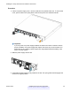
Table Of Contents
- Contents
- Chapter 1: Introduction
- Chapter 2: New in this release
- Chapter 3: Hardware models
- Chapter 4: Preinstallation checklist
- Chapter 5: Installing the Avaya Virtual Services Platform 7200 Series
- Installation checklist
- Installation fundamentals
- Electrostatic discharge
- Technical specifications
- Package contents
- Installing a power supply
- Removing a power supply
- Installing a fan module
- LED state definitions
- Installing the switch in an equipment rack
- Cable requirements for the VSP 7200
- Installation and removal of transceivers
- Console port pin assignments
- 40GBASE-QSFP+ ports
- Chapter 6: Translations of safety messages

The VSP 7254XTQ comes with an 800 W AC power supply and you can install a secondary power
supply for redundancy.
Important:
You must have either a power supply or a power supply cover in each bay to ensure proper
ventilation. Leaving a power supply bay unpopulated or uncovered impairs the ability of the fans
to cool the chassis.
Figure 4: AC power supply
The AC power supplies use an IEC 60320 C16 AC power cord connector. The AC power cord is in
close proximity to the hot air exhaust, and supports high operating temperatures.
Figure 5: IEC 60320 C16 connector
The following table describes the regulatory AC power specifications for the VSP 7200 Series
switches. Note that regulatory power specifications are based on the maximum rated capacity of the
power supplies and are not based on typical power consumption, which is typically lower.
Table 4: 460 W AC power specifications
7254XSQ
Input Current: 460 W/90 or 460/180 @88%,
5.8 A maximum at low input voltage
2.9 A maximum at high input voltage
Input Voltage (rms): 100–127 V or 200–240 V, 47–63 Hz (50–60 Hz
nominal)
Power Consumption: 460 W maximum
Thermal Rating: 1570 BTU/Hr maximum
Table continues…
Installing a power supply
October 2015 Installing the Avaya VSP 7200 Series 27
Comments on this document? infodev@avaya.com