
Installation Instructions


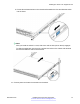


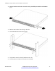


Table Of Contents
- Contents
- Chapter 1: Introduction
- Chapter 2: New in this document
- Chapter 3: Hardware models
- Chapter 4: Preinstallation checklist
- Chapter 5: Installing the Avaya Virtual Services Platform 7200 Series
- Installation checklist
- Installation fundamentals
- Electrostatic discharge
- Technical specifications
- Package contents
- Installing a power supply
- Removing a power supply
- Installing a fan module
- LED state definitions
- Installing the switch in an equipment rack
- Cable requirements for the VSP 7200
- Installation and removal of transceivers
- Console port pin assignments
- 40GBASE-QSFP+ ports
- Software limitations
- Chapter 6: Translations of safety messages

b. Pull the blue release latches on the chassis rails towards the front and slide the switch
into the frame.
Note:
After you install the switch in a rack, slide it out until the lock (shown above) engages.
To slide the switch back into the rack, push the blue locks on the chassis rails towards
the back and slide the switch into the frame.
12. Connect power and network connections to the switch.
Installing the switch in an equipment rack
November 2016 Installing the Avaya VSP 7200 Series 73
Comments on this document? infodev@avaya.com