
Installation Instructions


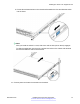


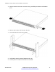


Table Of Contents
- Contents
- Chapter 1: Introduction
- Chapter 2: New in this document
- Chapter 3: Hardware models
- Chapter 4: Preinstallation checklist
- Chapter 5: Installing the Avaya Virtual Services Platform 7200 Series
- Installation checklist
- Installation fundamentals
- Electrostatic discharge
- Technical specifications
- Package contents
- Installing a power supply
- Removing a power supply
- Installing a fan module
- LED state definitions
- Installing the switch in an equipment rack
- Cable requirements for the VSP 7200
- Installation and removal of transceivers
- Console port pin assignments
- 40GBASE-QSFP+ ports
- Software limitations
- Chapter 6: Translations of safety messages

c. Push the end of the retaining latch out so it opens up.
d. Insert the bracket pins into the desired holes in the frame. The pin block accommodates
three different rack types. In the default position, the pin block fits into racks with square
holes. When retracted halfway, it fits into racks with large round holes. When fully
retracted, it fits into racks with small round holes.
Installing the switch in an equipment rack
November 2016 Installing the Avaya VSP 7200 Series 71
Comments on this document? infodev@avaya.com